Power source system, power supply control method for the power source system, power supply control program for the power source system, and computer-readable recording medium with the power supply control program recorded thereon

a power supply control and power supply control technology, applied in the direction of emergency power supply arrangements, secondary cells servicing/maintenance, etc., can solve the problems of inability to perform rescue operations to the nearest floor, margin is necessary, etc., to achieve the effect of increasing the target state quantity improving the state of charge and increasing the power supply capacity of the power storage devi

Inactive Publication Date: 2012-04-17
PANASONIC CORP
View PDF8 Cites 17 Cited by
  • Summary
  • Abstract
  • Description
  • Claims
  • Application Information

AI Technical Summary

Benefits of technology

[0012]It is an object of the present invention to provide a power source system that can realize at least a minimum backup function by temporarily increasing the power supply capacity of a power storage device when a power source device stops due to an accident or the like and also enables extension of service life and miniaturization of the power storage device, and also to provide a power supply control method for the power source system, a power supply control program for the power control system, and a computer-readable recording medium with the power supply control program recorded thereon.
[0014]With the above-described power source system, the stop determination unit determines whether the power source device has stopped, and where the power source device is determined to have stopped, the target state quantity of the power storage device can be increased. Thus, charge and discharge of the power storage device are controlled on the basis of a target state quantity that exceeds that during the operation of the power source device. Therefore, the state of charge of the power storage device can be improved over that during the operation of the power source device. As a result, the power supply capacity of the power storage device can be increased and the power necessary for the load device can be continuously supplied, in place of the power source device.
[0015]With the above-described power source system, the stop determination unit determines whether the power source device has stopped. Therefore, the power supply capacity of the power storage device can be increased only when the power source device stops. As a result, it is not necessary to increase the capacity of the power storage device in advance with consideration for the increase in power supply when the power source device stops, and the margin relating to the capacity of the power storage device can be reduced. As a result, miniaturization of the power storage device installed in the power source system can be facilitated.

Problems solved by technology

A problem encountered in this case is that because the charge to the battery power source is started after the operation of the power source device is restored and the rescue operation is performed after the charge is completed, the rescue operation to the nearest floor usually cannot be performed when a failure of the power source occurs, and the passengers are locked up in the elevator.
As a result, a margin is necessary for the capacity of the power source device that is used in the backup power source and a large power source device is required.

Method used


Image

  • Power source system, power supply control method for the power source system, power supply control program for the power source system, and computer-readable recording medium with the power supply control program recorded thereon
  • Power source system, power supply control method for the power source system, power supply control program for the power source system, and computer-readable recording medium with the power supply control program recorded thereon
  • Power source system, power supply control method for the power source system, power supply control program for the power source system, and computer-readable recording medium with the power supply control program recorded thereon

Examples


embodiment 1

[0024](Embodiment 1)

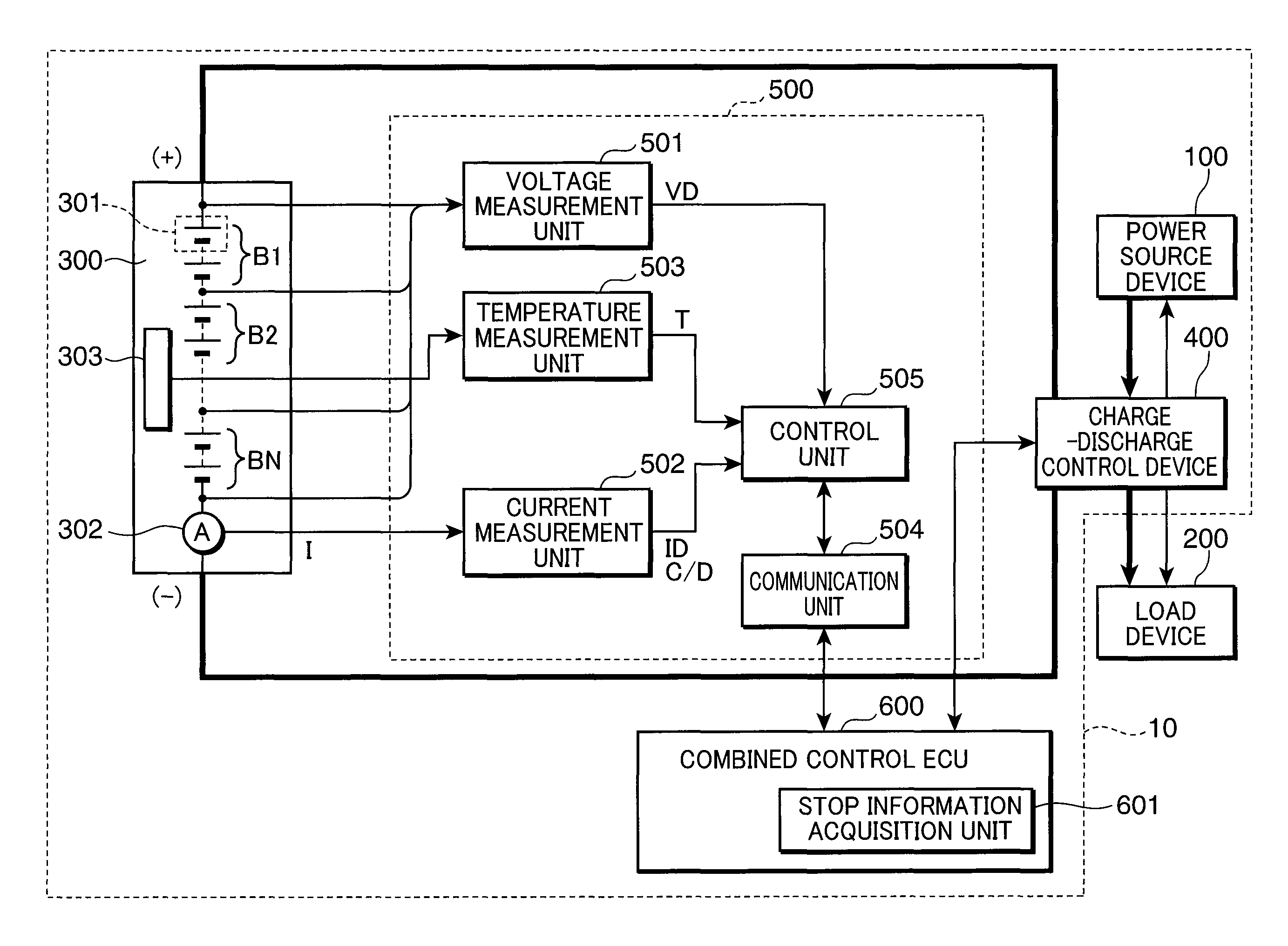
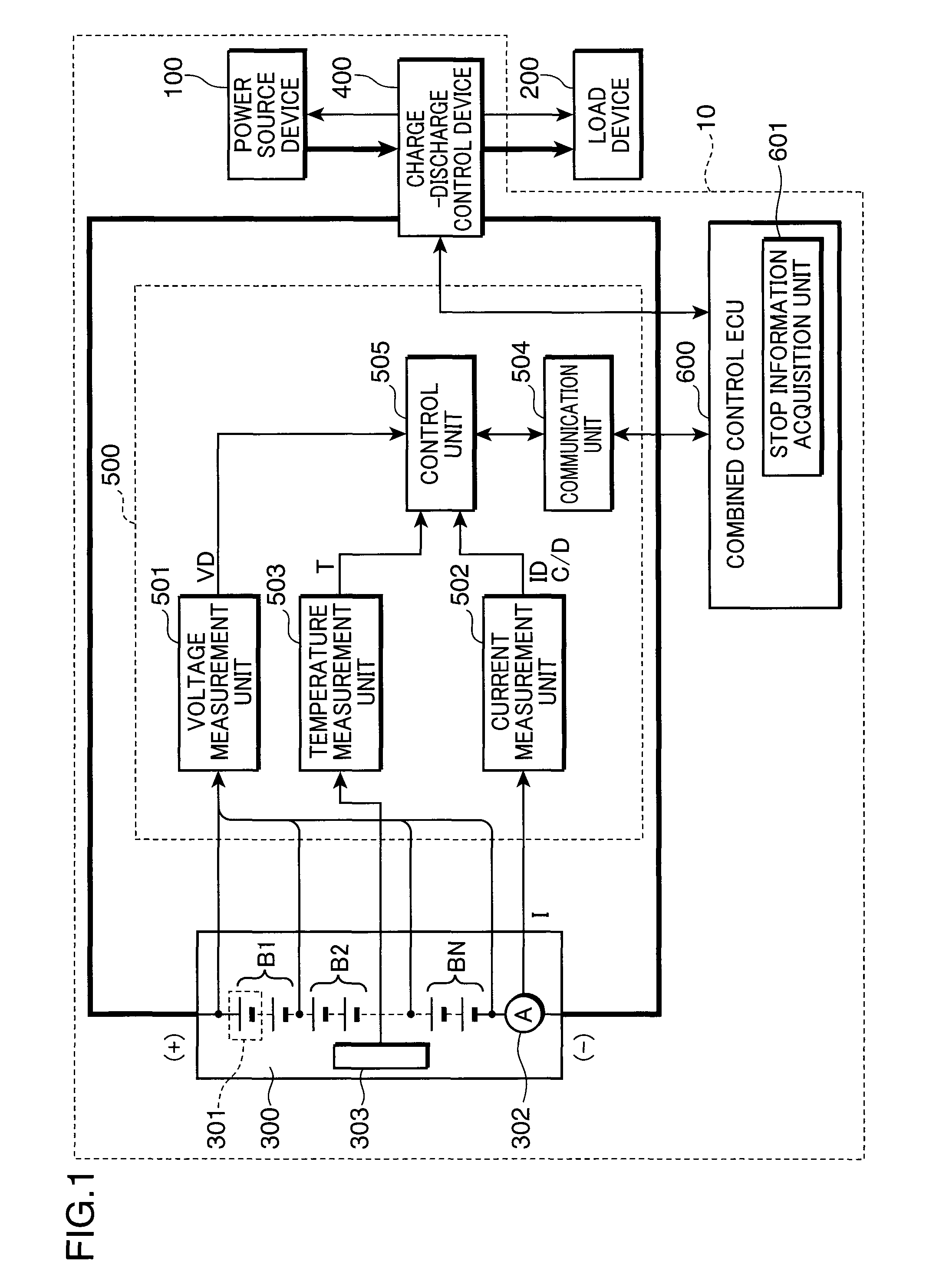
[0025]FIG. 1 is a block diagram illustrating the configuration of a power source system of Embodiment 1 of the present invention. As shown in FIG. 1, a power source system 10 of the present embodiment is provided with a power source device 100, a power storage device 300, a charge-discharge control device 400, a power supply control device 500, and a combined control ECU (Electronic Control Unit) 600.

[0026]The power source device 100 is, for example, a commercial power source and also includes a generator that uses an engine as a mechanical power source, and the like. A load device 200 includes various units that are driven by the supplied power.

[0027]The power storage device 300 stores extra power from the power source device 100 and regenerative electric power generated by the load device 200 and supplies, when necessary, the power stored therein to the load device 200. The power storage device 300 is configured by N storage element blocks B1, B2, . . . , BN th...

embodiment 2

[0068](Embodiment 2)

[0069]Embodiment 2 of the invention will be described below with reference to the drawings. In the above-described Embodiment 1, in a case where power is supplied from the power storage device 300 to the load device 200 when the power source device 100 stops, the power supply capacity of the power storage device 300 is increased by raising the target state quantity of the power storage device 300. By contrast, in Embodiment 2 of the invention, in addition to raising the target state quantity of the power storage device 300 as in Embodiment 1, where the load device 200 has a plurality of power consumption modes, the load device 200 is shifted to a low power consumption mode when the power source device 100 stops. As a result, the power required by the load device 200 when the power source device 100 stops is reduced and the state of charge of the power storage device 300 is further enhanced, thereby increasing the power supply capacity of the power storage device ...

embodiment 3

[0092](Embodiment 3)

[0093]Embodiment 3 of the invention will be described below with reference to the drawings. In the above-described Embodiment 1, in a case where power is supplied from the power storage device 300 to the load device 200 when the power source device 100 stops, the power supply capacity of the power storage device 300 is increased by raising the target state quantity of the power storage device 300. Furthermore, in the above-described Embodiment 2, the power necessary for the load device 200 is reduced and power supply capacity of the power storage device 300 is increased by shifting the load device 200 to a low power consumption mode when the power source device 100 stops.

[0094]By contrast, in Embodiment 3 of the invention, in addition to raising the target state quantity of the power storage device 300 as in Embodiment 1, the power charged to the power storage device 300 when the power source device 100 stops in increased. As a result, the state of charge of the ...


PUM


Abstract

The present invention provides a power source system that increases the power supply capacity of a power source device and continuously supplies the power necessary for a load device when a power source device stops. A control unit has a state quantity setting unit that sets a first target state quantity indicating a state of charge of the power storage device that is to be a target value when charge and discharge of the power storage device are controlled. When the power source device stops, the state quantity setting unit can change the first target state quantity to a second target state quantity that is to be a target value exceeding the first target state quantity and can increase the target state quantity of the power storage device. As a result, when the power source device stops, charge and discharge of the power storage device are controlled on the basis of the target state quantity exceeding that during the operation of the power source device. Therefore, the state of charge of the power storage device can be improved over that during the operation of the power source device. As a result, the power supply capacity of the power source device can be increased and the power necessary for the load device can be continuously supplied, in place of the power source device.

Description

RELATED APPLICATIONS[0001]This application is the U.S. National Phase under 35 U.S.C. §371 of International Application No. PCT / JP2008 / 050209, filed on Jan. 10, 2008, which in turn claims the benefit of Japanese Application No. 2007-017830, filed on Jan. 29, 2007, the disclosures of which Applications are incorporated by reference herein.TECHNICAL FIELD[0002]The present invention relates to a power source system that is provided with a power storage device that supplies power when a power source device such as a commercial power source stops, a power supply control method for the power source system, a power supply control program for causing a computer to execute the power supply control method for the power source system, and a computer-readable recording medium with the power supply control program for the power source system recorded thereon.BACKGROUND ART[0003]Power storage devices have recently attracted attention and found practical use as backup power sources for commercial ...

Claims


Application Information

Patent Timeline
Patent Type & Authority Patents(United States)
IPC IPC(8): H02J7/00H02J1/10
CPCB66B5/027H01M10/44H02J7/0063H02J9/061H02J7/0047Y02E60/10H02J7/0048H02J7/007182
Inventor IIDA, TAKUMAKIMURA, TADAO
Owner PANASONIC CORP
Why Eureka
Try Eureka