Moving image decoding apparatus and moving image coding apparatus

a technology of moving image and decoding apparatus, which is applied in the direction of color television with bandwidth reduction, television systems, instruments, etc., can solve the problems of unsuitable use, inability of the receiving side to buffer coded data for a long time, and disturbance of the display of moving images, so as to improve the quality of image frames and improve the quality of decoding images

Inactive Publication Date: 2012-04-17
MITSUBISHI ELECTRIC CORP
View PDF9 Cites 8 Cited by
  • Summary
  • Abstract
  • Description
  • Claims
  • Application Information

AI Technical Summary

Benefits of technology

[0011]The present invention is made in order to solve the above-mentioned problems, and it is therefore an object of the present invention to provide a moving image decoding apparatus which, when receiving image data coded using a moving image coding method including inter frame prediction by way of a transmission line having errors, and decoding the image data, decodes the image data using coded data which is transmitted thereto after a delay in response to, for example, a request for retransmission of the coded data without lengthening the time required to decode the image data since it is received, by utilizing the time interval which elapses until it is referred to at the time of the decoding of another image frame after decoded, thereby reducing the degradation in the quality of the decoded image data, and a moving image coding apparatus which is suited to the moving image coding apparatus.
[0013]Therefore, the present embodiment offers an advantage of being able to improve the quality of a decoded image frame to be referred to in which a loss or an error has occurred, and which is to be referred to at the time of the decoding of another image frame, and to improve the quality of image frames which are decoded with reference to the image frame to be referred to.

Problems solved by technology

Although TCP (Transmission Control Protocol) is used as a protocol for enabling related art moving image decoding apparatus to carry out such processes, it is unsuitable for uses, such as transmission of moving images in real time since the time of arrival of retransmitted packets is not guaranteed.
However, in general, the receive side cannot buffer coded data for a long time in reception of a moving image in real time since the buffering time is added to a delay which occurs between the transmission of the coded data at the transmit side and the playback of the coded data.
Therefore, a problem is that when the related art moving image decoding apparatus cannot decode inputted coded data about a moving image at a high speed because of the processing capability of the decoder, the related art moving image decoding apparatus cannot carry out the process of receiving and decoding coded data at a predetermined timing and therefore the display of the moving image is disturbed.
Another problem is that when a long delay time is introduced into transmission of coded data by the transmission line, and it takes several frame times for correct coded data which is transmitted in response to, for example, a request for retransmission of the coded data to reach the related art moving image decoding apparatus, even when the correct coded data is received in the meantime, a large buffer for storing all the received data and a high-speed decoder which can decode the correct coded data at a high speed so as to offset the delay of several frame times long are needed.

Method used


Image

  • Moving image decoding apparatus and moving image coding apparatus
  • Moving image decoding apparatus and moving image coding apparatus
  • Moving image decoding apparatus and moving image coding apparatus

Examples


embodiment 1

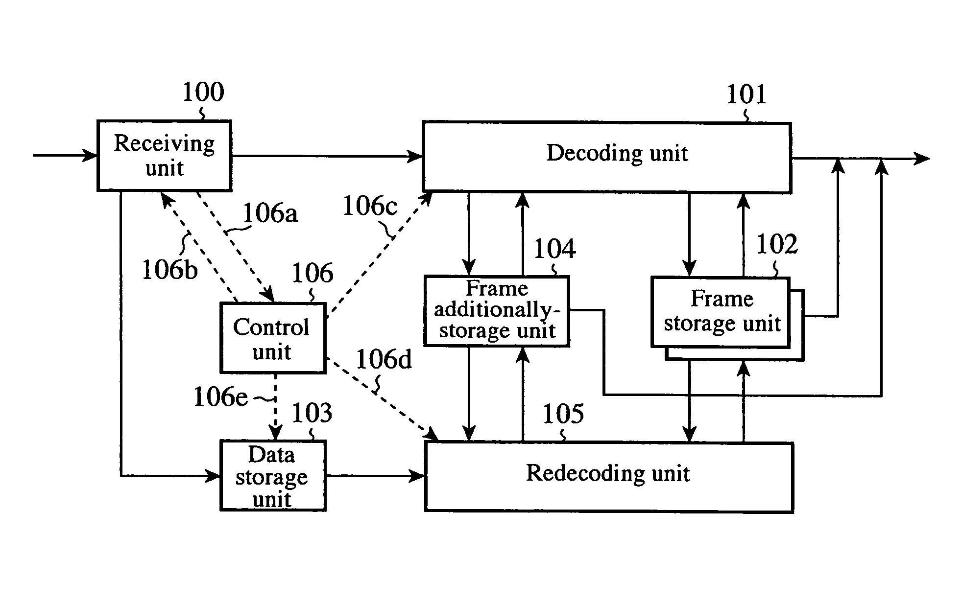
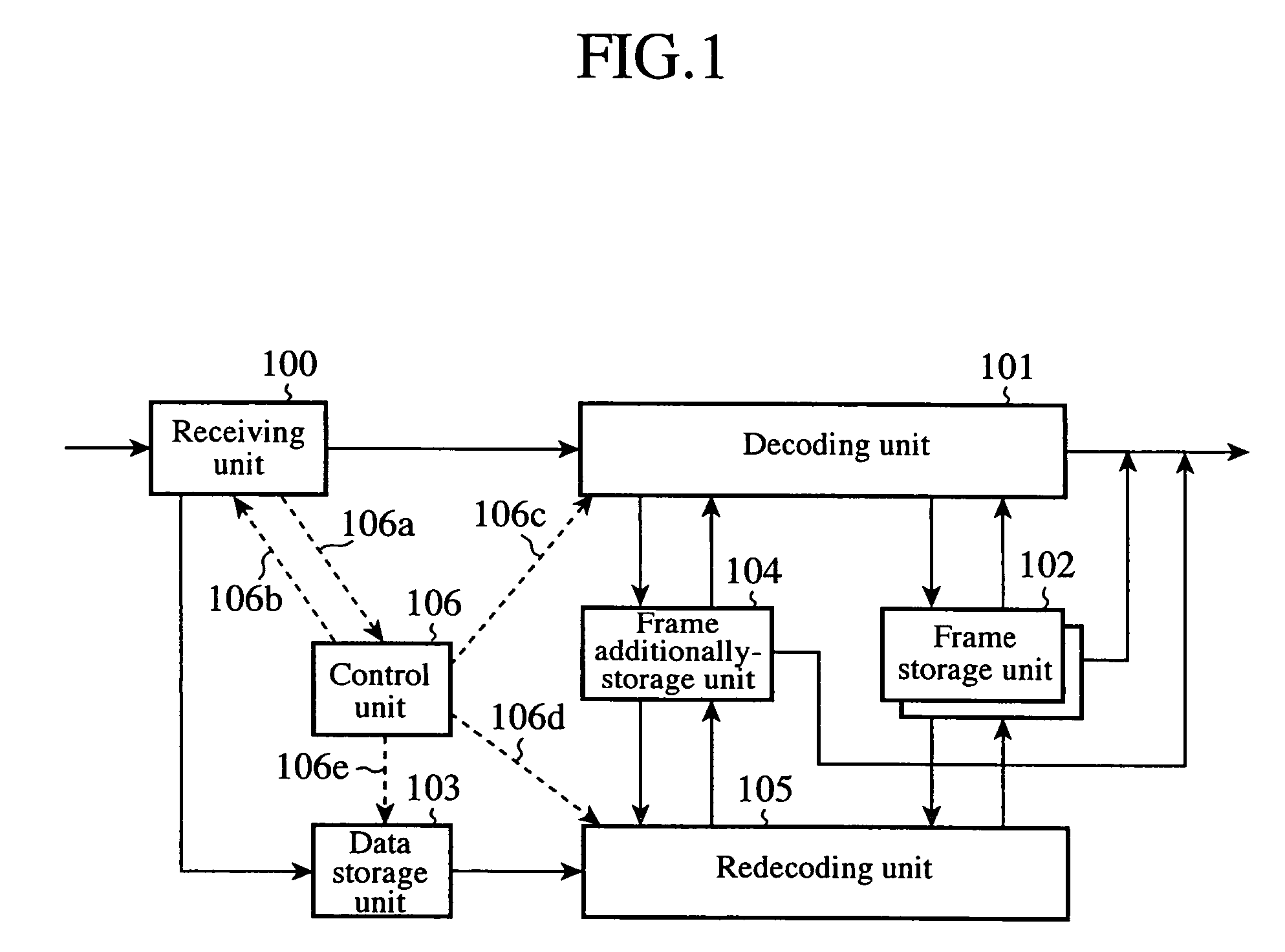
[0033]FIG. 1 is a block diagram showing the structure of a moving image decoding apparatus in accordance with embodiment 1 of the present invention. The moving image decoding apparatus shown in FIG. 1 is provided with a receiving unit 100, a decoding unit 101, a frame storage unit 102, a data storage unit 103, a frame additionally-storage unit 104, a redecoding unit 105, and a control unit 106.

[0034]The receiving unit 100 receives a plurality of types of image frames from a transmission line, and notifies reception state information about a data loss or error in coded data which constitutes the image frames to the control unit 106. The decoding unit 101 decodes the plurality of types of image frames received by the receiving unit 100 by referring to one or more image frames which have been decoded and which are required for the decoding of the plurality of types of image frames. The data storage unit 103 stores an image frame which consist of coded data having a data loss or error w...

embodiment 2

[0095]In above-mentioned embodiment 1, the data storage time and decoding time of the data storage unit 103 are fixed. In contrast, in accordance with this embodiment 2, the opportunity to receive and redecode correct coded data is increased by changing the storage time during which coded data is stored in the data storage unit 103 according to the structure of reference frames and frames to be referred to, i.e., the frame structure of GOP, and the decoding time of the decoding unit 101, as will be explained below.

[0096]FIG. 6 is a diagram showing the operation timing of the decoding unit 101 and that of the redecoding unit 105, and data stored in the frame storage unit 102 and data stored in the frame additionally-storage unit 104, like FIG. 4 of above-mentioned embodiment 1. The structure of reference frames and frames to be referred in GOP differs from that shown in FIG. 4 of above-mentioned embodiment 1 in that the M value of GOP changes from 3 to 2 on the way.

[0097]FIG. 7 is a ...

embodiment 3

[0115]In this embodiment 3, a case where a buffer area for storing one more image frame is additionally disposed, and therefore the number of image frames in each of which the propagation of degradation in the image quality is suppressed is increased will be explained.

[0116]FIG. 10 is a diagram showing the operation timing of the decoding unit 101 and that of the redecoding unit 105, and data stored in the frame storage unit 102 and data stored in a frame additionally-storage unit 114, like FIG. 4. FIG. 10 differs from FIG. 4 in that the frame additionally-storage unit 114 has two buffers (i.e., buffers 2a and 2b).

[0117]FIG. 11 is a block diagram showing the structure of a moving image decoding apparatus in accordance with embodiment 3 of the present invention, and the moving image decoding apparatus in accordance with embodiment 3 differs from that of above-mentioned embodiment 1 in that it has the frame additionally-storage unit 114 instead of the frame additionally-storage unit 1...


PUM


Abstract

A data storage unit (103) stores an image frame in which an image frame which consists of coded data having a data loss or error received by a receiving unit (100) and complementary coded data which is received by receiving unit at a later time are rearranged into normal sequence. A redecoding unit (105) decodes the image frame stored in the data storage unit (103) with reference to one or more already-decoded image frames required for the decoding, and stores the decoded image frame in a frame additionally-storage unit (104). A decoding unit (101) decodes an image frame with reference to an image frame stored in either a frame storage unit (102) or the frame additionally-storage unit 104 according to a command from a control unit (106).

Description

BACKGROUND OF THE INVENTION[0001]1. Field of the Invention[0002]The present invention relates to a moving image decoding apparatus which receives and decodes coded data, and a moving image coding apparatus which codes image data and transmits coded data. More particularly, it relates to a moving image decoding apparatus which temporarily starts decoding coded data transmitted thereto and decodes the coded data again when they become complete, and replaces the previously-decoded data with the newly-decoded data in a case where an error occurs in the coded data transmitted thereto, some data are missing from the coded data, or there occur fluctuations in the transmission time of the coded data in a transmission line, and therefore some of all the coded data are not transmitted thereto at the time when it has to complete the reception of the coded data required and to start decoding the coded data at a predetermined timing in order to perform display of the decoded data normally, there...

Claims


Application Information

Patent Timeline
Patent Type & Authority Patents(United States)
IPC IPC(8): H04B1/66H04N19/159H04N19/164H04N19/166H04N19/423H04N19/50H04N19/503H04N19/577H04N19/59H04N19/65H04N19/89
CPCH04N19/114H04N19/136H04N19/895H04N19/423H04N19/40H04N19/44
Inventor MURAYAMA, SHUHOMMA, HIROSHISHIBATA, KUNIO
Owner MITSUBISHI ELECTRIC CORP
Why Eureka
Try Eureka