Emergency unlocking device for a parking lock

a technology of emergency unlocking and parking lock, which is applied in the direction of mechanical control devices, process and machine control, instruments, etc., can solve the problems of unnecessary wear of the transfer device, potential corrosion risk, and technical principle known from the prior art, and achieve the effect of reducing structural complexity and low nois

Inactive Publication Date: 2012-04-24
ZF FRIEDRICHSHAFEN AG
View PDF25 Cites 8 Cited by
  • Summary
  • Abstract
  • Description
  • Claims
  • Application Information

AI Technical Summary

Benefits of technology

[0013]Against this background the purpose of the present invention is to provide an emergency release device for manually actuating the parking lock of a shift-by-wire gear-change transmission, which overcomes the aforesaid disadvantages of the prior art. The emergency release device should in particular be reliable and inexpensive, and should have advantages particularly in relation to lower noise emission, improved corrosion protection, and in relation to easier and less error-prone assembly and adjustment of the transfer means.
[0017]In this way, the secondary pivoting lever—following rotation of the transmission shifting shaft during normal operation of the transmission—can move back and forth within the actuation range of the primary pivoting lever without the primary pivoting lever and the transfer device of the emergency release actuation—i.e. for example the cable for the emergency release of the parking lock—connected thereto being deflected away from their rest position and moved as well. Thus, undesired noise due to unnecessary movement of the transfer device is prevented, and likewise, the transfer device, since it is not moving, is subjected to less wear and corrosion. The defined connection between the transfer device and the primary pivoting lever also facilitates assembly of the emergency release mechanism and errors in the adjustment of the transfer device can be avoided.
[0020]In a further, particularly preferred embodiment of the invention, the primary and secondary pivoting levers are mounted coaxially on the transmission housing. The coaxial mounting of the primary and secondary pivoting levers reduces the structural complexity and enables the two pivoting levers to be mounted together in the area of, or directly on the transmission shifting shaft. Preferably, the spring of the unidirectional coupling element is also arranged on the common mounting of the primary and secondary pivoting levers, i.e. for example on the transmission shifting shaft between the primary and secondary pivoting levers.
[0021]A further preferred embodiment of the invention provides that the unidirectional coupling element is formed as an abutment arranged on the secondary pivoting lever for the primary pivoting lever or, optionally, an abutment arranged on the primary pivoting lever for the secondary pivoting lever. In this way the unidirectional coupling element between the primary and secondary pivoting levers can be made particularly simply, robustly and inexpensively, preferably as a bent tab extending from the secondary (or the primary) pivoting lever, against which, in the event of emergency release, the primary (or secondary) pivoting lever comes in contact to move the secondary pivoting lever along with the primary pivoting lever.
[0022]The invention can be realized regardless of how the mechanical transfer element between the gear-change transmission and the emergency release actuator is designed. According to a preferred embodiment of the invention, however, the transfer element is in the form of a cable. The cable can be laid freely between the transmission and the emergency release actuator and also has advantages in relation to low noise conduction through solid bodies.

Problems solved by technology

In normal operation, however, the problem then arises that the shifting shaft in the transmission and the emergency release pivoting lever connected thereto are in each case moved at the same time by the transmission hydraulics during shifting operations of the automatic transmission, whereby the mechanical emergency release transfer device between the transmission and the emergency release actuator—for example the cable—would also be moved.
But this is undesirable, since it results in annoying noise in the emergency release transfer device and can also lead to unnecessary wear of the transfer device.
However, this technical principle known from the prior art is first of all potentially susceptible to corrosion in the area of the open, loose connection between the end of the cable and the pivoting lever.
Moreover, precisely because of the loose end of the cable undesired noise can again be produced, which can then be conducted via the cable itself into the vehicle's interior.
Owing to the only loose connection between the cable end and the pivoting lever, this known emergency release system is also prone to maladjustments during assembly, for example if during assembly the free standing length of the cable is measured wrongly.

Method used


Image

  • Emergency unlocking device for a parking lock
  • Emergency unlocking device for a parking lock
  • Emergency unlocking device for a parking lock

Examples


Embodiment Construction

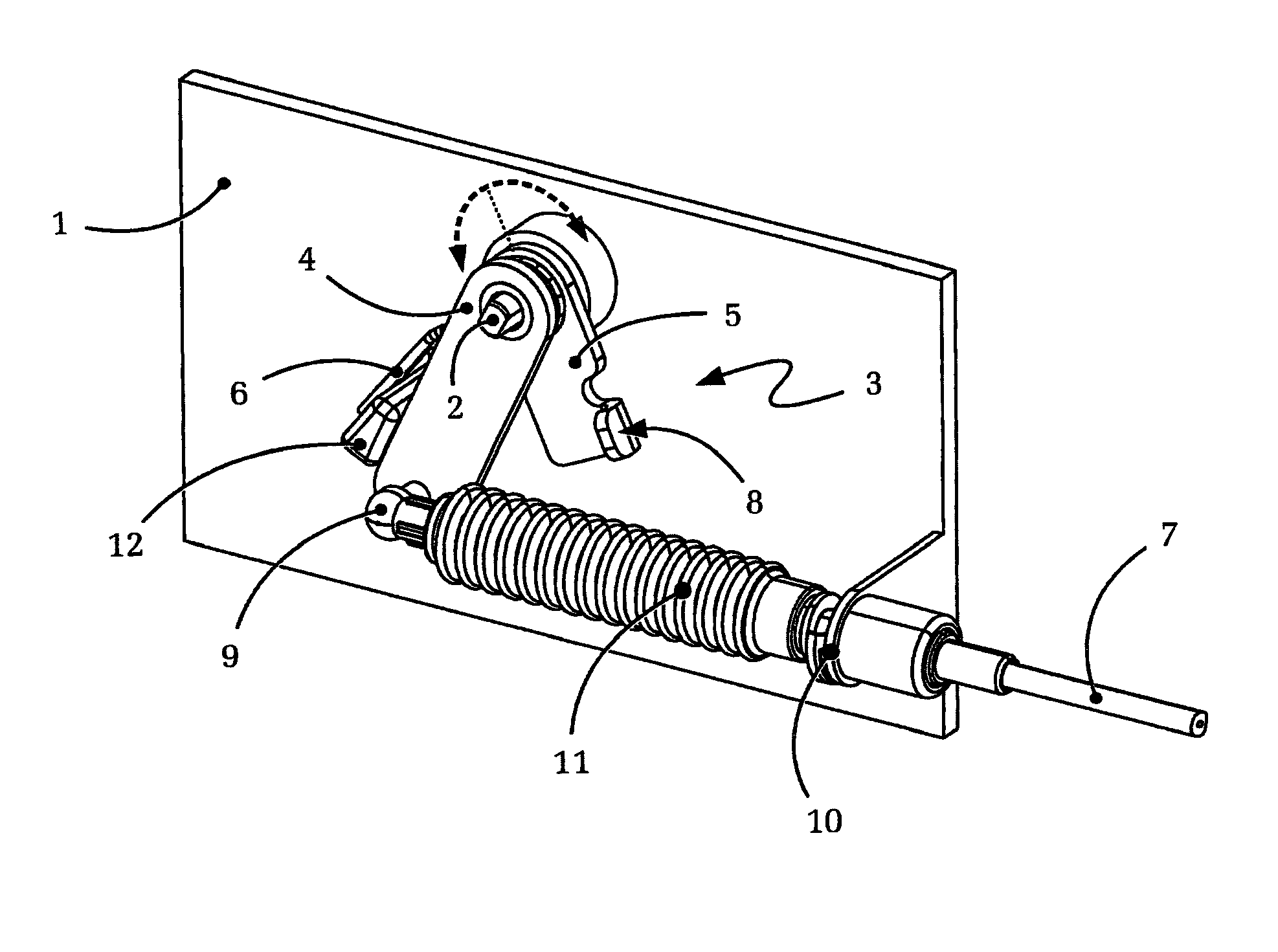
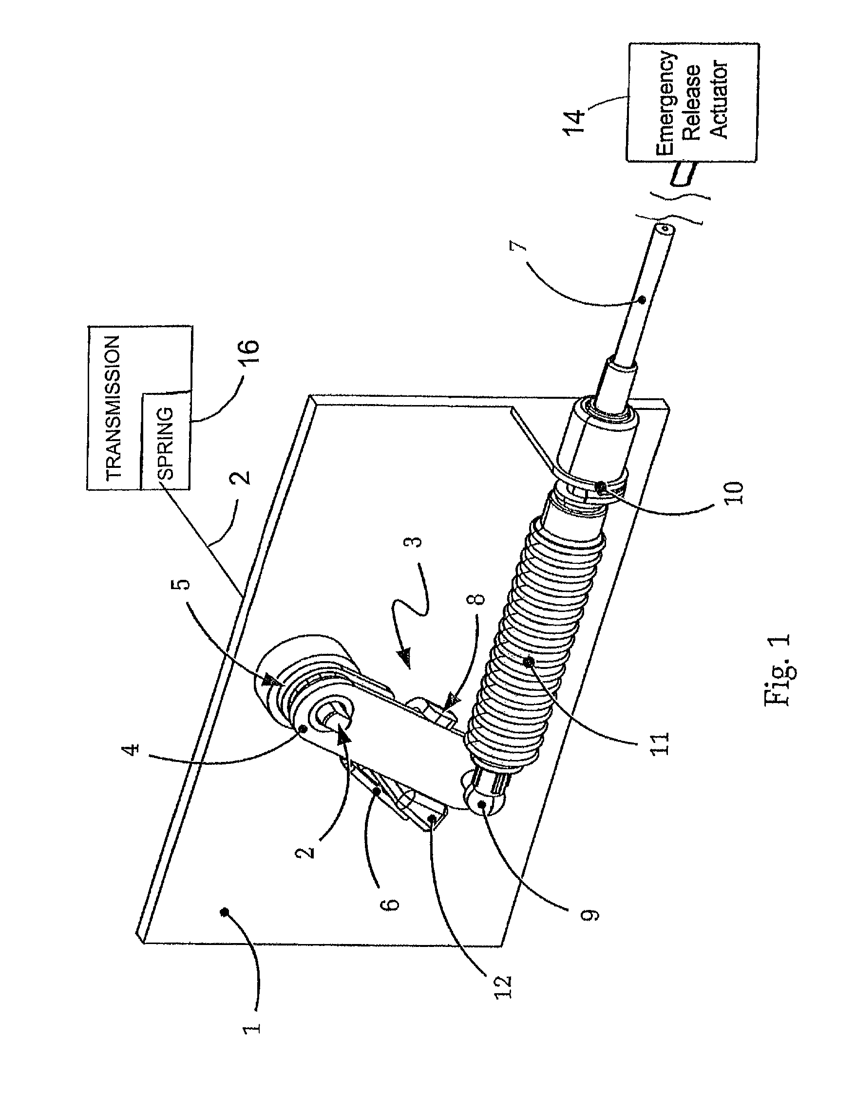
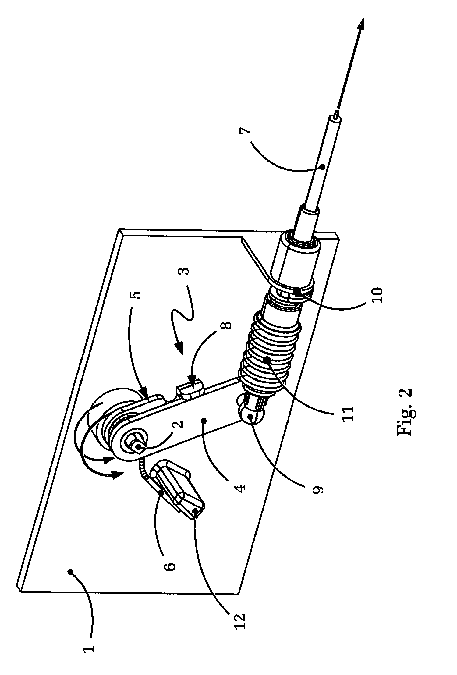
[0027]FIG. 1 shows a schematic, isometric representation of the pivoting lever mechanism of an embodiment of an emergency release device according to the present invention.

[0028]The figure shows, first, a section of the wall of the transmission housing 1 and the outward-projecting end of the shifting shaft 2 of the automatic transmission that passes through the transmission housing 1. Also to be seen is the pivoting lever mechanism 3 which, in the embodiment illustrated, consists of the primary pivoting lever 4, the secondary pivoting lever 5 connected in a rotationally fixed manner to the transmission shifting shaft 2, and a lever spring 6 arranged axially between the primary pivoting levers 4 and the secondary pivoting lever 5. In this case the primary pivoting lever 4 is mounted coaxially with the secondary pivoting lever 5 but can rotate, as such, freely relative to the transmission shifting shaft 2 and relative to the secondary pivoting lever 5.

[0029]The primary pivoting lever ...


PUM


Abstract

An emergency release device for manual actuation of the parking lock of a shift-by-wire transmission. The emergency release device comprises a mechanical transfer device located between an emergency release actuator and the transmission and engages a pivoting lever mechanism arranged on a transmission shifting shaft. A characterizing feature of the emergency release device is that the pivoting lever mechanism comprises a primary pivoting lever connected to the transfer device, a secondary pivoting lever connected to the transmission and a unidirectional coupling element located between the primary and the secondary pivoting levers. The advantage of this device relates to reduced susceptibility to corrosion, wear and noise emission and easier correct adjustment of the transfer device during assembly, while a separate prestressing mechanism for the cable of the emergency parking lock release can be omitted.

Description

[0001]This application is a National Stage completion of PCT / DE2008 / 050039 filed Dec. 5, 2008, which claims priority from German patent application serial no. 10 2008 006 398.3 filed Jan. 28, 2008.FIELD OF THE INVENTION[0002]The invention concerns an emergency release device for the manual actuation of the parking lock of a gear-change transmission, for example an automatic shift-by-wire transmission.BACKGROUND OF THE INVENTION[0003]Parking locks are always used when non-mechanical components are involved in the transmission of the driving force in motor vehicles, especially in automatic transmissions with a hydrodynamic torque converter. In this way, despite the non-mechanical connection between the drivetrain and the motor of the motor vehicle, the drive wheels can be locked and unintentional rolling away of the vehicle can be prevented. For this purpose, as a result of an actuation signal issued by the driver, the parking lock blocks the transmission output shaft connected in a r...

Claims


Application Information

Patent Timeline
Patent Type & Authority Patents(United States)
IPC IPC(8): G05G5/08G05G5/00B60W10/10
CPCF16H63/3491Y10T74/20116Y10T74/20085
Inventor GIEFER, ANDREASRAKE, LUDGER
Owner ZF FRIEDRICHSHAFEN AG
Why Eureka
Try Eureka