
Piezoelectric driven control valve

a piezoelectric actuator and control valve technology, applied in the direction of diaphragm valves, valve housings, engine diaphragms, etc., can solve the problems of piezoelectric elements, piezoelectric actuators b>40/b> cannot be applied with a very large precompression load, and shorten the product lifetime, etc., to achieve the effect of preventing damage to piezoelectric elements, extending the lifetime, and relatively easy assembly

Active Publication Date: 2012-04-24
FUJIKIN INC
View PDF25 Cites 18 Cited by
  • Summary
  • Abstract
  • Description
  • Claims
  • Application Information

AI Technical Summary

Benefits of technology

The present invention is a piezoelectric driven control valve that includes a body with a valve seat, a metal diaphragm, a tubular actuator box, a stem, a piezoelectric actuator, and a precompression mechanism. The piezoelectric actuator is supported by a diaphragm presser and a precompression part, which applies a constant pressure to the piezoelectric elements. The precompression part can be a shaft-shaped part or a disc spring. The technical effects of the invention include improved control accuracy, reduced power consumption, and improved reliability.

Problems solved by technology

However, the stacked-type piezoelectric actuator 40 suffers from a problem caused by the fact that the extension and retraction rate of the piezoelectric elements 40b is greater than that of the displacement member 40c when the piezoelectric actuator 40 is extended and retracted, which causes a tensional force to be applied between piezoelectric elements 40b adjacent each other when the piezoelectric actuator 40 is retracted, which causes damage to the piezoelectric elements 40b and shortens the product lifetime.
Accordingly, the piezoelectric actuator 40 also cannot be applied with a very large precompression load because, otherwise, it may suffer from the problem wherein the piezoelectric elements 40b are damaged by application of a large tensile stress.
This gap causes a generation force, when the piezoelectric actuator 40 is extended, to not be transmitted reliably and successfully to the actuator box 36, which makes high-precision flow control difficult.
However, such a control valve has not yet been developed.

Method used


Image

  • Piezoelectric driven control valve
  • Piezoelectric driven control valve
  • Piezoelectric driven control valve

Examples


Embodiment Construction

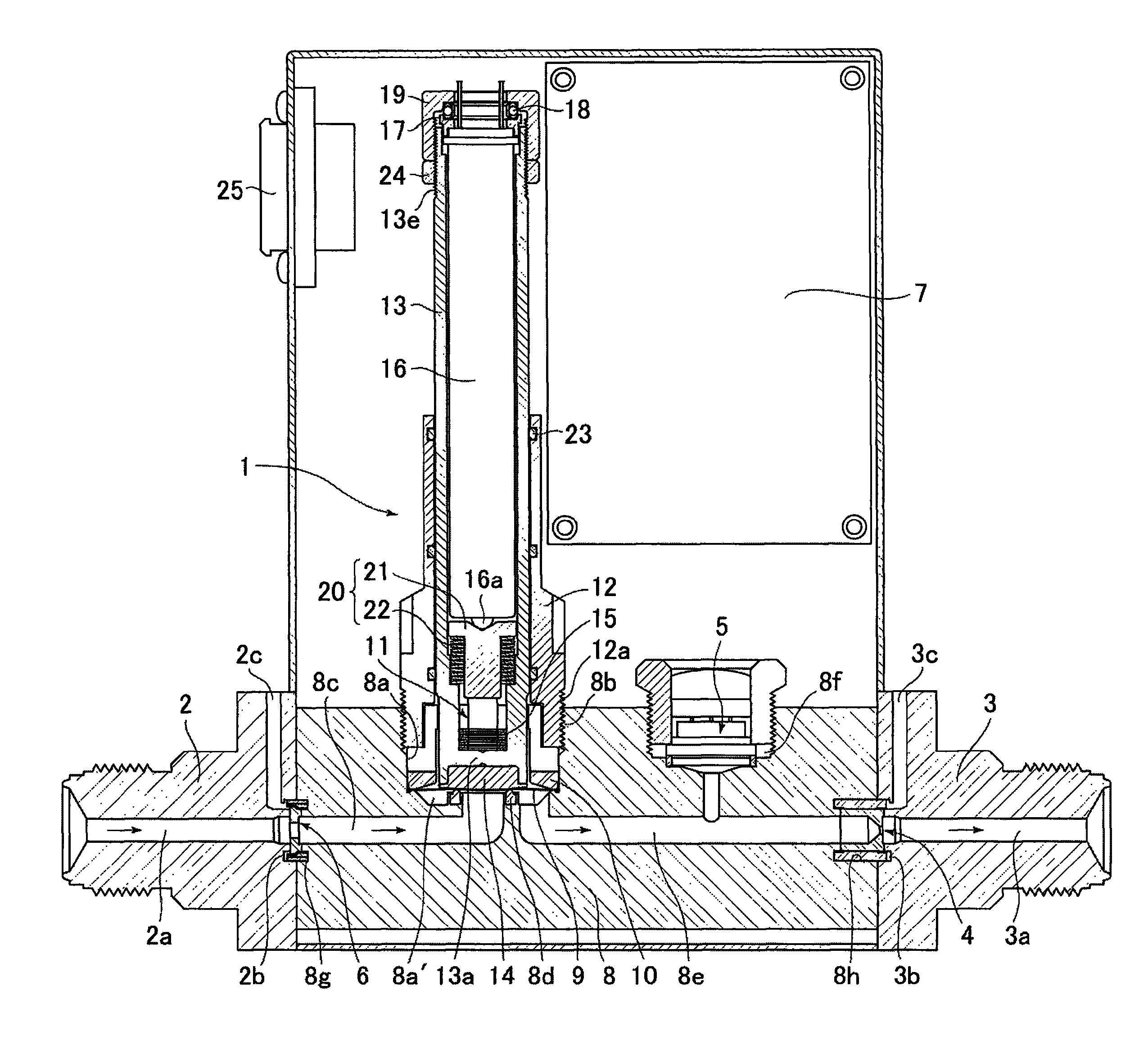
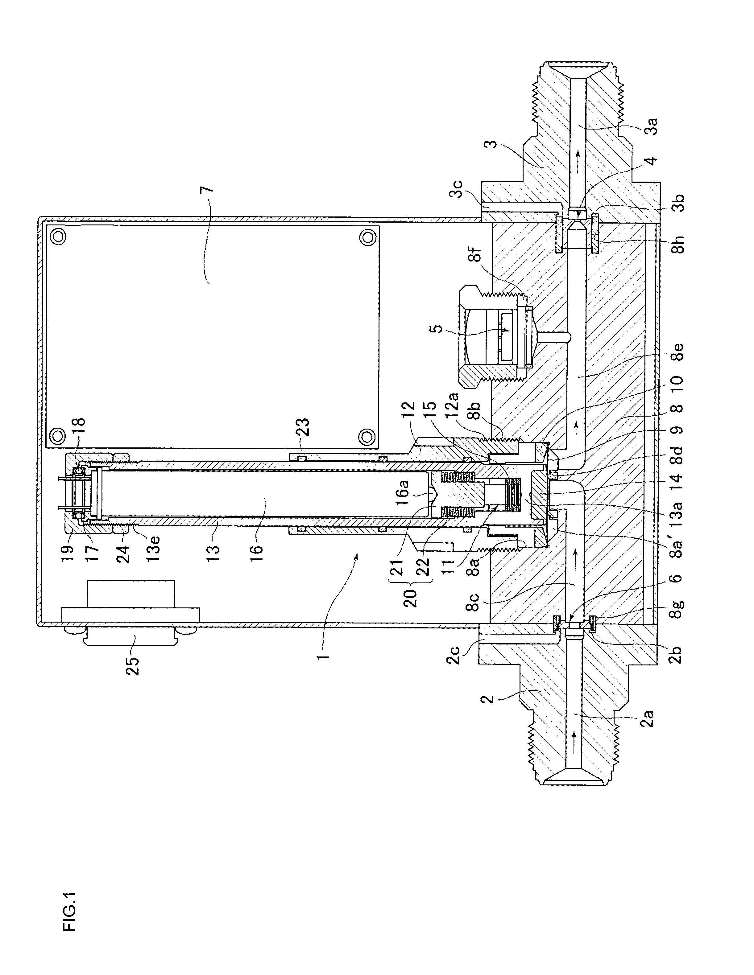
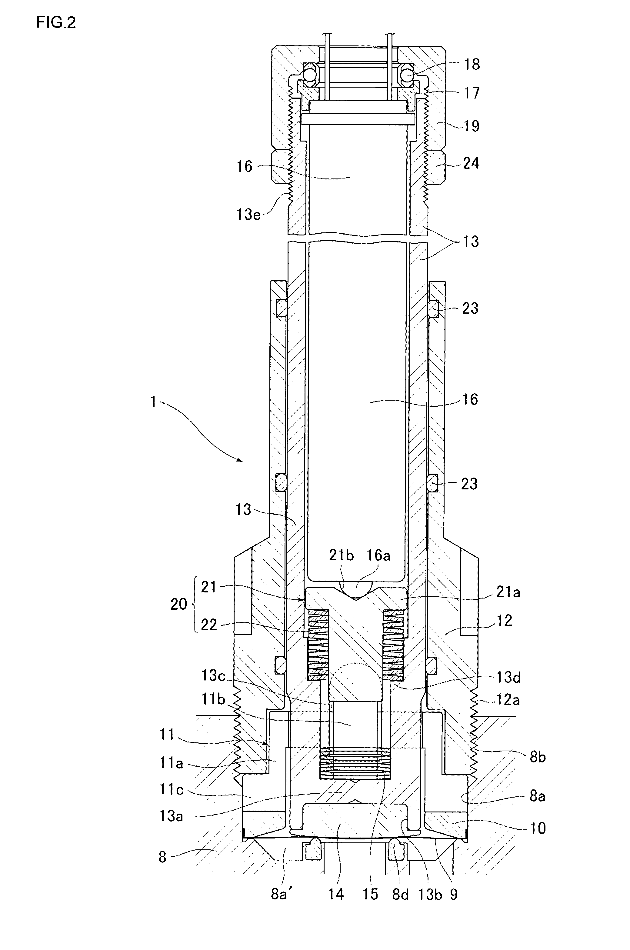
[0030]Embodiments of the present invention will hereinafter be described in detail with reference to the drawings. FIG. 1 shows a piezoelectric driven control valve 1 according to an illustrative first embodiment of the present invention, employed in a pressure type flow control device. The pressure type flow control device includes: the piezoelectric driven control valve 1; an inlet port block 2 connected on the upstream side of the piezoelectric driven control valve 1; an outlet port block 3 connected on the downstream side of the piezoelectric driven control valve 1; an orifice 4 for flow control provided on the downstream side of the piezoelectric driven control valve 1; a pressure sensor 5 provided on the upstream side of the orifice 4 to detect the upstream side pressure of the orifice 4; a gasket filter 6 provided on the upstream side of the piezoelectric driven control valve 1; and a control circuit 7 for controlling the piezoelectric driven control valve 1, in which the flo...


PUM


Abstract

Stable flow control is made possible even under high-temperature environments by relieving tensional force applied to a piezoelectric element when a piezoelectric actuator is retracted. Thus, a piezoelectric driven control valve includes: a body having a valve seat; a metal diaphragm to contact with and separate from the valve seat; an actuator box supported ascendably and descendably on the body; a split base fixed to the body; a disc spring pressing and urging the actuator box downward to bring the metal diaphragm into contact with the valve seat; and a piezoelectric actuator housed inside the actuator box and that extends upward with application of voltage to press the actuator box upward against the elastic force of the disc spring, and a precompression mechanism, for applying a compression force constantly to piezoelectric elements in the piezoelectric actuator, provided between the split base and the piezoelectric actuator.

Description

[0001]This is a National Phase Application in the United States of International Patent Application No. PCT / JP2008 / 000572 filed Mar. 13, 2008, which claims priority on Japanese Patent Application No. 2007-090082, filed Mar. 30, 2007. The entire disclosures of the above patent applications are hereby incorporated by reference.TECHNICAL FIELD OF THE INVENTION[0002]The present invention relates to improved piezoelectric driven control valves that are used as control valves in pressure type flow control devices, or in flow control units of a mass flow controller, such as are provided mainly in a gas control line of semiconductor manufacturing equipment, or the like. In particular, the present invention relates to a piezoelectric driven control valve that relieves a tensional force applied to a piezoelectric element when a piezoelectric actuator is retracted so as to prevent the piezoelectric element from being damaged and the piezoelectric driven control valve makes possible high-precis...

Claims


Application Information

Patent Timeline
Patent Type & Authority Patents(United States)
IPC IPC(8): F16K31/02
CPCF16K7/14F16K31/007F16K27/0236F16K1/36H01L21/02
Inventor SAWADA, YOHEIHIRATA, KAORUDOHI, RYOSUKENISHINO, KOUJIIKEDA, NOBUKAZU
Owner FUJIKIN INC
Learn More