Moving fluid energy recovery system

a technology of moving fluid and energy recovery, which is applied in the direction of non-positive displacement fluid engines, liquid fuel engine components, road transportation emission reduction, etc., can solve the problems of complex and difficult manufacturing of known devices, and efforts have not been successful in overcoming problems associated with prior known wind or water machines, etc., to achieve low manufacturing cost, easy and efficient manufacturing and marketing, and low price of sale

Active Publication Date: 2012-04-24
PENTA POWER TURBINES INC
View PDF26 Cites 10 Cited by
  • Summary
  • Abstract
  • Description
  • Claims
  • Application Information

AI Technical Summary

Benefits of technology

[0023]It is another object of the present invention to provide a new and improved moving fluid energy recovery system that may be easily and efficiently manufactured and marketed.
[0024]An even further object of the present invention is to provide a new and improved moving fluid energy recovery system that has a low cost of manufacture with regard to both materials and labor, and which accordingly is then susceptible of low prices of sale to the consuming public, thereby making such moving fluid energy recovery system economically available to the buying public.
[0026]Even still another object of the present invention is to provide a moving fluid energy recovery system for generating electricity through rotational motion produced by moving fluid. This allows for an efficient and inexpensive way to produce electricity while in a moving vehicle or if located in an area with a fluid flow.

Problems solved by technology

Some of these known devices are complex and difficult to manufacture.
While these systems and devices fulfill their respective, particular objectives and requirements, the aforementioned patents do not describe a moving fluid energy recovery system that allows generating electricity through rotational motion produced by moving fluid.
But these, and similar, efforts have not been successful in overcoming the problems associated with the prior known wind or water machines.
As a consequence, wind or water machines have not been commercially attractive and have not achieved substantial acceptance in the marketplace.
The fewer the propeller blades, the more efficient the machines become at high wind speeds but the less efficient they are at lower wind speeds.
Furthermore, it is not practical to position the windmill on a moving vehicle.
Because the blades of horizontal-axis windmills are coupled indirectly to an electric generator which is effective only at a constant design speed, and because the blades themselves become unsafe at high speeds, the horizontal-axis windmills have been capable of utilizing only a small percentage of the theoretically-available power in the wind.
The multi-blade windmills have high starting torque at low wind speeds, harvesting up to 30% of the kinetic energy from the wind but become very inefficient at high wind speeds.
To maintain a near constant level of torque to drive the generator has required either: complex controls, in the case of pitch control, or intricate blade designs, in the case of stall control, both of which are expensive to build and maintain.
These requirements have combined to make windmills economically unattractive except in areas where alternative forms of electricity generation are not readily available.
They have problems with gyroscopic vibration when the machine veers with changing wind direction.
They are vulnerable to high bending moments at the base or root of the blades as each blade passes by or into the wind-shade of the supporting mast as well as when being braked during tempest conditions.
These bending moments lead to frequent blade replacements and high maintenance costs.
Because of their massive structures, these machines, of necessity, are remotely located miles from the area of power usage, thus necessitating construction of expensive power grids to transport the energy produced to the point of consumption, (generally large cities).
Consequently, an approximate eight to ten percent of the power generated never reaches its destination due to line and transformer losses.
Lastly, because of opposition from environmentalists with regard to the esthetics in natural settings as well as prohibition from municipal regulating authorities due to safety hazards associated with these large-prop machines in populated areas, many areas which would be ideal for generating wind energy, such as atop large buildings, are simply off-limits due to opposing design constraints.
These known systems are complex, with control systems and inefficient rotor designs, thereby not making them practical to be placed and integrated into a moving vehicle.

Method used


Image

  • Moving fluid energy recovery system
  • Moving fluid energy recovery system
  • Moving fluid energy recovery system

Examples


Embodiment Construction

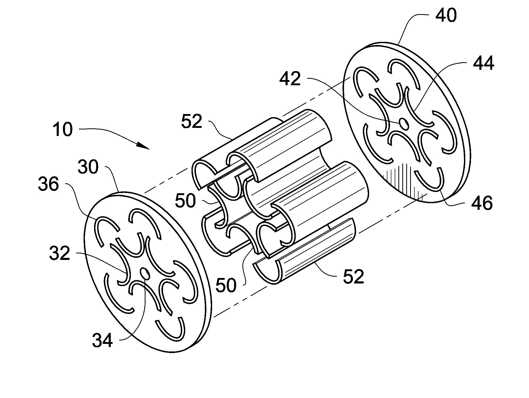
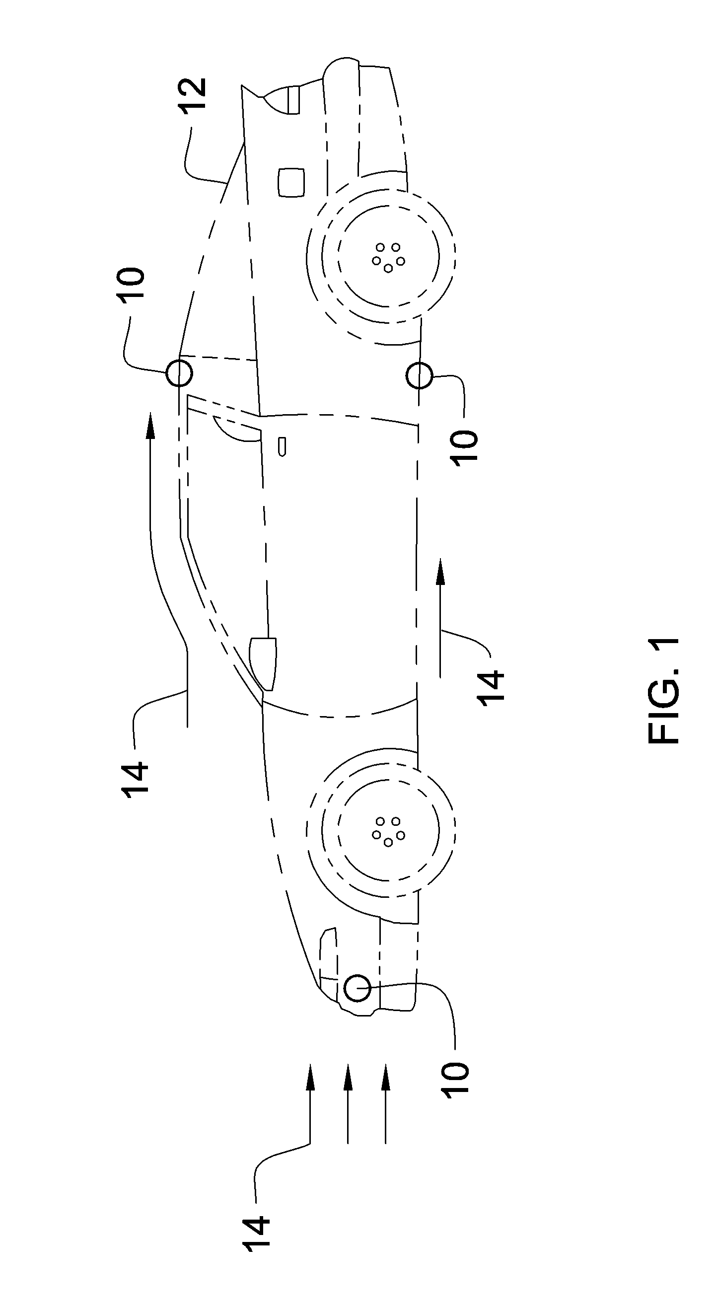
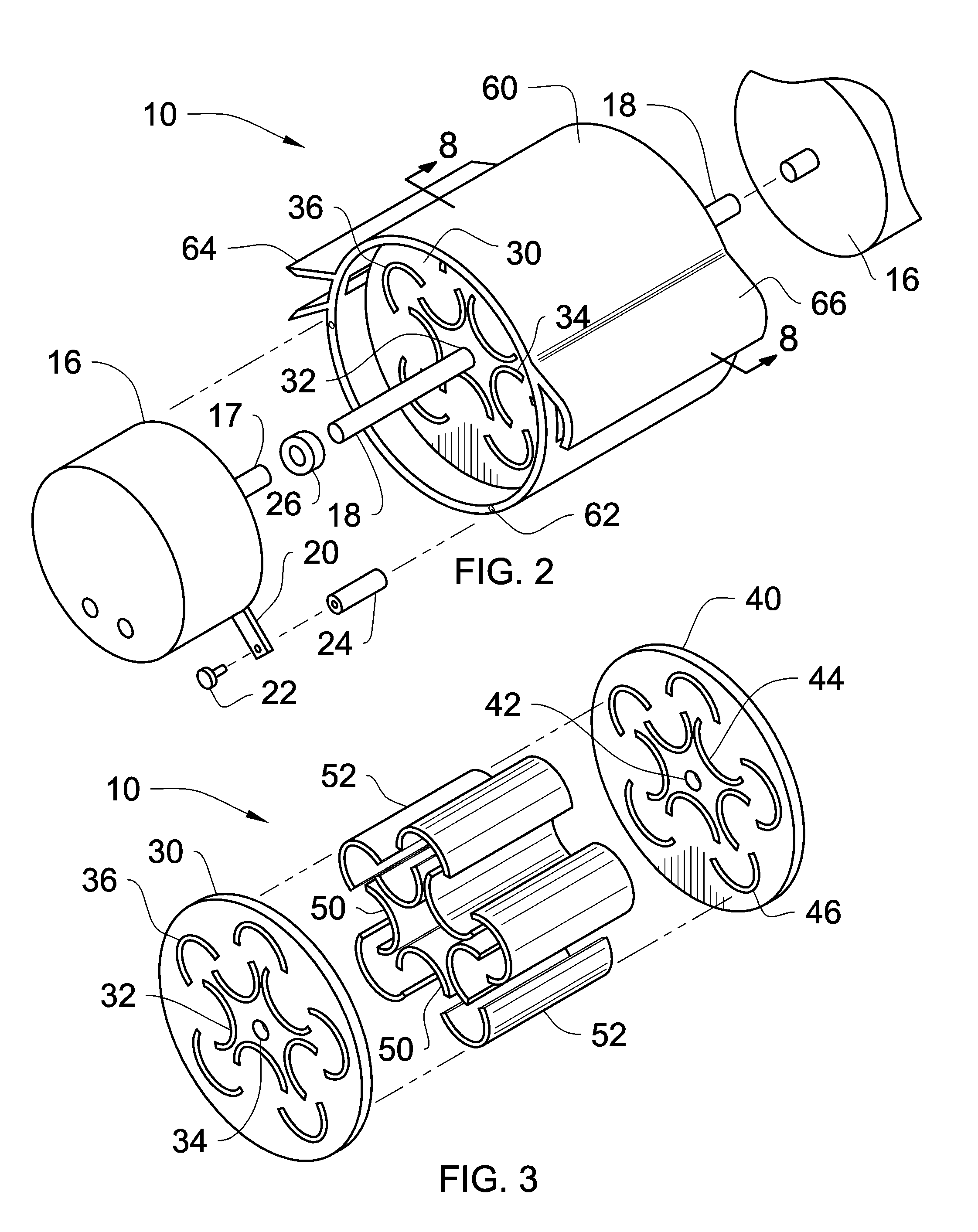
[0042]Referring now to the drawings and particularly to FIGS. 1-11, a preferred embodiment of the moving fluid energy recovery system of the present invention is shown and generally designated by the reference numeral 10.

[0043]In FIG. 1, a new and improved moving fluid energy recovery system 10 of the present invention for generating electricity through rotational motion produced by moving fluid 14 either by weather or a vehicle 12 in motion is illustrated and will be described. More particularly, the moving fluid energy recovery system 10 is a stand alone unit that is placed in the area of fluid flow 14 or can be removably attached to a moving vehicle 12 producing a fluid flow 14 when the vehicle is in motion. The fluid flow 14 can be any flowable fluid, such as but not limited to water, air, wind, liquids, slurries, dirt, and the like. The vehicle 12 can be any know traveling vehicle, such as but not limited to a motor vehicle, automobile, motorcycle, bicycle, aircraft, spacecraft...


PUM

PropertyMeasurementUnit
inlet angleaaaaaaaaaa
lengthaaaaaaaaaa
diameteraaaaaaaaaa

Abstract

A moving fluid energy recovery system for generating electricity through rotational motion produced by positioning the present invention in a fluid flow produced by nature or a moving vehicle. The moving fluid energy recovery system has first and second end plates, a plurality of elongated inner vanes, a plurality of elongated outer vanes, and shaft to drive an electricity generating device. The inner and outer vanes each have a substantially curved profile featuring a curve side and an open side. The first and second end plates each has a central bore defined therethrough, a plurality of inner vane slots each shaped to receive a corresponding inner vane, and a plurality of outer vane slots each shaped to receive a corresponding outer vane. The inner vane slots are orientated with the curve side toward the central bore, and the outer vane slots are orientated with the open side toward the central bore with the free ends of adjacent inner vanes positioned in the open side of the outer vane slots.

Description

CROSS-REFERENCE TO RELATED APPLICATION[0001]Not applicableFEDERALLY SPONSORED RESEARCH[0002]Not applicableSEQUENCE LISTING OR PROGRAM[0003]Not applicableBACKGROUND OF THE INVENTION[0004]1. Field of the Invention[0005]The present invention relates to a moving fluid energy recovery system for use in connection with generating electricity through rotational motion produced by moving fluid either by weather or a vehicle in motion.[0006]2. Description of the Prior Art[0007]Moving fluid energy recovery systems are desirable for transferring kinetic energy of a moving fluid to rotational motion for driving an electric generator or alternator. It can be appreciated that a fluid energy recovery system that is inexpensive and simple to manufacture is very beneficial to the production of electricity. These systems can be easily purchased, installed and maintained by the average person.[0008]The ever increasing price of oil and gasoline, and the increasing global demand for electricity, in conc...

Claims


Application Information

Patent Timeline
Patent Type & Authority Patents(United States)
IPC IPC(8): F03D7/06
CPCB60K16/00F03D13/20F03D9/25B60K2016/006F05B2240/941Y02E10/725Y02E10/728Y10T29/49336Y10S415/907Y10S416/09Y10T29/4932Y02T10/90F03D3/0454F03D9/32F03D15/00Y02E10/74Y02T10/7072
Inventor MOORE, BRIAN
Owner PENTA POWER TURBINES INC
Why Eureka
Try Eureka