Amplifying apparatus

a technology of amplifiers and amplifiers, applied in the direction of amplifiers with semiconductor devices only, amplifiers with semiconductor devices, amplifiers, etc., can solve the problems of affecting the improvement of power efficiency, difficult to obtain excellent linearity, and high saturation voltage of output transistors, so as to improve linearity and low gate-source voltage , the effect of low power supply use efficiency

Active Publication Date: 2012-04-24
YAMAHA CORP
View PDF8 Cites 81 Cited by
  • Summary
  • Abstract
  • Description
  • Claims
  • Application Information

AI Technical Summary

Benefits of technology

[0008]The invention has been conducted in view of the above-described problem of the conventional art. It is an object of the invention to provide an amplifying apparatus in which the power efficiency can be improved.
[0010]According to the invention, the high and low voltages are supplied to the outputting section. One of the voltages is a fixed voltage, and the other voltage is switched between the first and second voltages. In the case where the amplitude of the output signal is small and the level of the signal does not become beyond a predetermined value, therefore, the fixed voltage and the second voltage are applied to the outputting section. Namely, in the case where the output signal has a small amplitude, a voltage similar to that in the case of a large amplitude is used without switching the one voltage. Consequently, the gate-source voltages of the p- and n-channel transistors can be made high, and the ON resistances of the transistors in the saturation region can be reduced. As a result, the power loss can be reduced.
[0013]According to the invention, the other voltage is switched between the first and second voltages, and the one voltage is fixed. Therefore, the predetermined value is set in the side of the other voltage while setting the ground potential as a reference, and, depending on whether the other voltage is beyond the predetermined value or not, the switching between the first and second voltages is performed. Consequently, the power loss can be reduced without distorting the output signal,
[0015]According to the invention, when the level of the output signal repeatedly becomes beyond (exceeds and falls below) the predetermined value for a short time period, the other voltage can be fixed to the first voltage, and frequent voltage switching can be prevented from occurring.
[0020]In the case where the absolute value of the second voltage is 1 V or less, if also the fixed voltage that is the one voltage is switched similarly with the other voltage, the gate-source voltages of the p- and n-channel transistors during a small-amplitude period of the output signal are 2 V at the maximum. When the load impedance is assumed to be 8 to 16Ω, a low gate-source voltage is disadvantageous. When the linearity is considered, the amplitude of the output signal which can be output during the small-amplitude period is greatly smaller than ±1 V, and the use efficiency of the power supply is not high. By contrast, in the invention, the one voltage is set as a fixed voltage, and hence the gate-source voltages of the p- and n-channel transistors during a small-amplitude period of the output signal can be 3 V at the maximum. As a result, the linearity can be improved, and the use efficiency of the power supply can be enhanced.

Problems solved by technology

In the case where the load impedance is low, i.e., for example, 8 or 16Ω and the gate-source voltage Vgs is small, it is difficult to obtain excellent linearity, and hence the saturation voltages of the output transistors become high.
Therefore, an output voltage which can be output by the low-voltage operation is smaller in amplitude than the power supply voltages of ±1 V, and there arises a technical problem in that the improvement of the power efficiency is impeded.

Method used


Image

  • Amplifying apparatus
  • Amplifying apparatus
  • Amplifying apparatus

Examples


Embodiment Construction

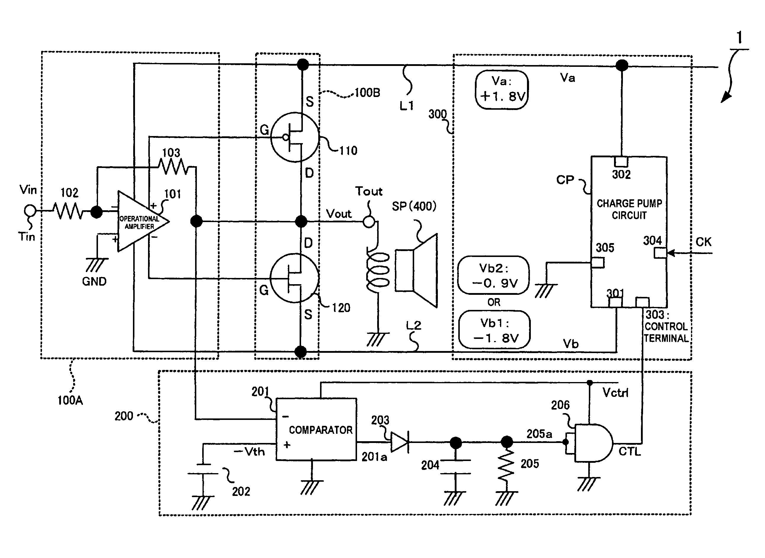
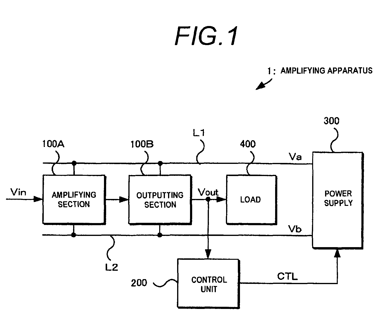
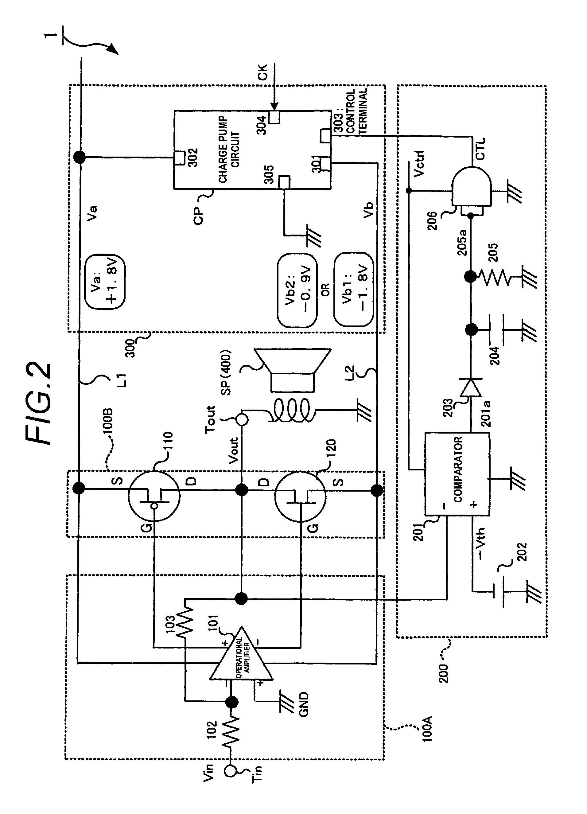
[0033]An embodiment of the invention will be described with reference to the drawings. FIG. 1 is a conceptual block diagram conceptually showing the whole configuration of an amplifying apparatus 1 of the embodiment, and FIG. 2 is a block diagram schematically showing the detailed configuration of the amplifying apparatus 1 of the embodiment.

[0034]As shown in FIG. 1, the amplifying apparatus 1 of the embodiment includes: an amplifying section 100A which voltage-amplifies an input signal Vin, and which outputs the amplified signal; an outputting section 100B which current-amplifies the output of the amplifying section 100A, and which supplies an output signal Vout to a load 400; a high-potential power supply line L1 through which a high voltage Va is supplied; a low-potential power supply line L2 through which a low voltage Vb is supplied; and a power supply 300 which supplies the high voltage Va and the low voltage Vb to the amplifying section 100A and the outputting section 100B. I...


PUM


Abstract

An amplifying apparatus amplifies an input signal supplied to an input terminal and outputs an output signal from an output terminal. The apparatus includes a high-potential power supply line through which a high voltage is supplied; a low-potential power supply line through which a low voltage is supplied; a control unit; and a power supply in which one of the high and low voltages is a fixed voltage, and which generates, as the other of the high and low voltages, one of a first voltage in which a polarity of the fixed voltage is inverted, and a second voltage which is closer to the ground potential than the first voltage is. The control unit controls the power supply to cause the other of the high and low voltages to be switched between the first voltage and the second voltage in accordance with a signal level of the output signal.

Description

BACKGROUND OF THE INVENTION[0001]1. Technical Field[0002]The present invention relates to the technical field of amplifying apparatuses in which the power consumption can be reduced.[0003]2. Background Art[0004]WO00 / 72546 discloses a technique in which, in an amplifying apparatus that operates with two kinds of high and low power supply voltages from each of power supplies respectively having positive and negative polarities, the power supply voltages are controlled in accordance with the amplitude of a signal.[0005]FIG. 11 shows an example of an amplifying apparatus for adjusting power supply voltages in accordance with the amplitude of a signal. In the example, high power supply voltages are used at ±2 V, and low power supply voltages for improving the output efficiency are used at ±1 V which are a half of the high power supply voltages of ±2 V. The configuration is employed because, owing to the property of a so-called charge pump, the two-division structure causes the circuit op...

Claims


Application Information

Patent Timeline
Patent Type & Authority Patents(United States)
IPC IPC(8): H03F3/04
CPCH03F1/0233H03F3/185H03F3/303H03F2200/511
Inventor IWAMATSU, MASAYUKI
Owner YAMAHA CORP
Why Eureka
Try Eureka