Conversion of an antenna to multiband using current probes

a multi-band, current probe technology, applied in the field of communication systems, can solve the problems of limiting the number of additional antennas, the risk of existing capabilities being compromised, and the limited area available on the roof of buildings, which often serve as antenna placement locations, so as to improve the voltage standing wave ratio and increase the frequency capability

Inactive Publication Date: 2012-04-24
THE UNITED STATES OF AMERICA AS REPRESENTED BY THE SECRETARY OF THE NAVY
View PDF9 Cites 2 Cited by
  • Summary
  • Abstract
  • Description
  • Claims
  • Application Information

AI Technical Summary

Benefits of technology

[0006]In accordance with one aspect of the present disclosure, a method for converting an existing antenna capable of generating H fields having a first signal line into a multi-signal line antenna with increased frequency capabilities is provided, comprising: mounting a first current probe having a designated frequency range about a periphery of the existing antenna; coupling a second signal line to the first current probe; and performing at least one of transmitting and receiving via at least one of the first and second signal lines, wherein the mounting of the first current probe to the existing antenna improves a voltage standing wave ratio (VSWR) of the existing antenna and the second signal line operates as an independent signal line for signal reception / transmission within the designated frequency range.

Problems solved by technology

In many situations the available real estate limits the number of additional antennas that may be added to a site.
For example, the area available on building rooftops, and exterior surfaces of automobiles, aircraft, and vessels, which often serve as antenna placement locations, is particularly limited.
However, the existing antennas are known to perform “well” and the replacement of such antennas often requires a significant investment of capital and resources, and also runs the risk of the existing capabilities being compromised in view of the “newer” antenna.

Method used


Image

  • Conversion of an antenna to multiband using current probes
  • Conversion of an antenna to multiband using current probes
  • Conversion of an antenna to multiband using current probes

Examples


Embodiment Construction

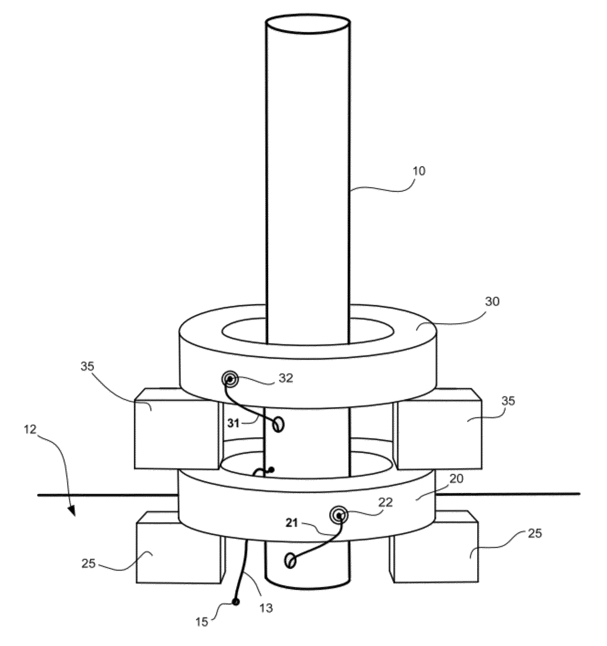
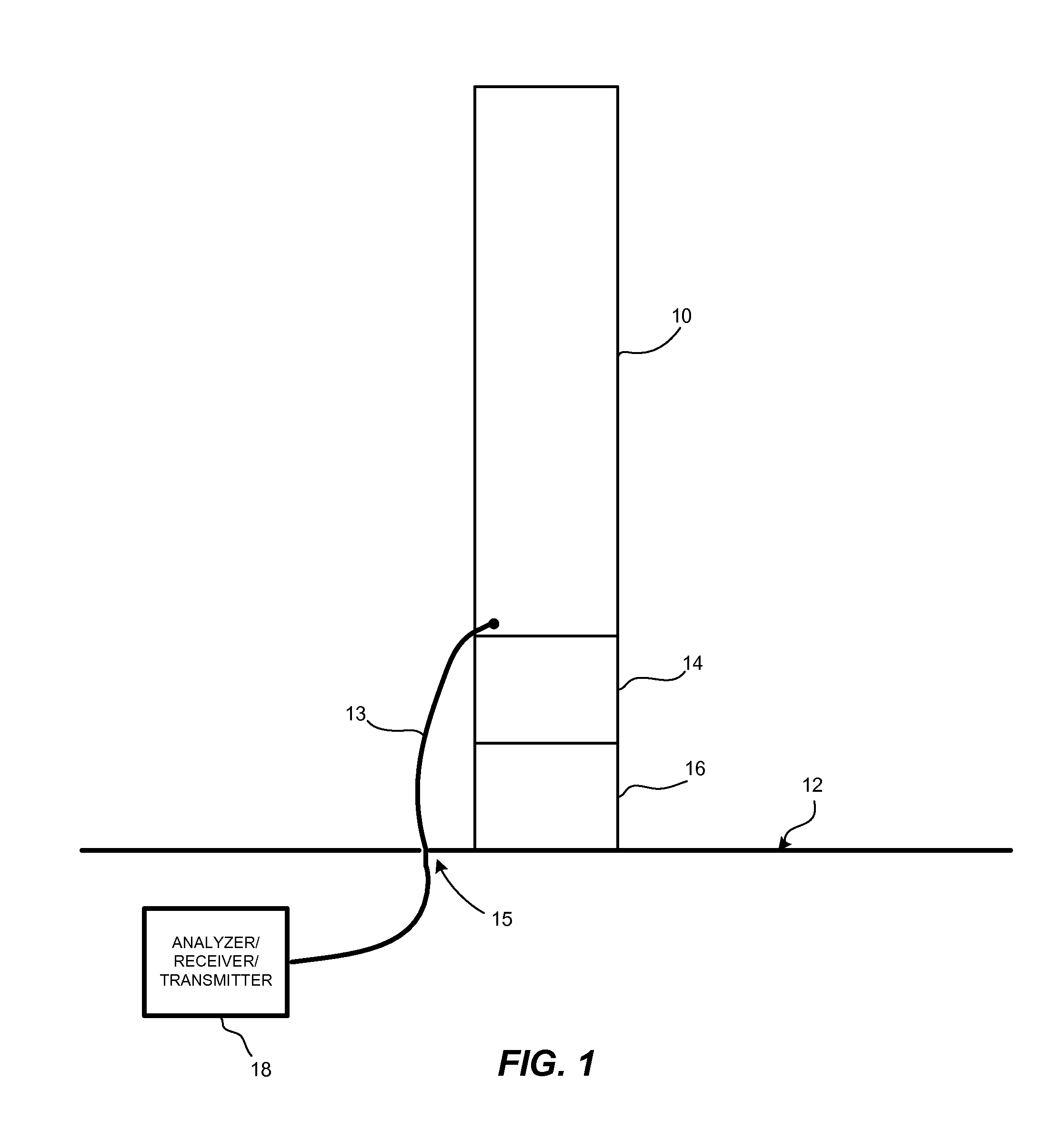
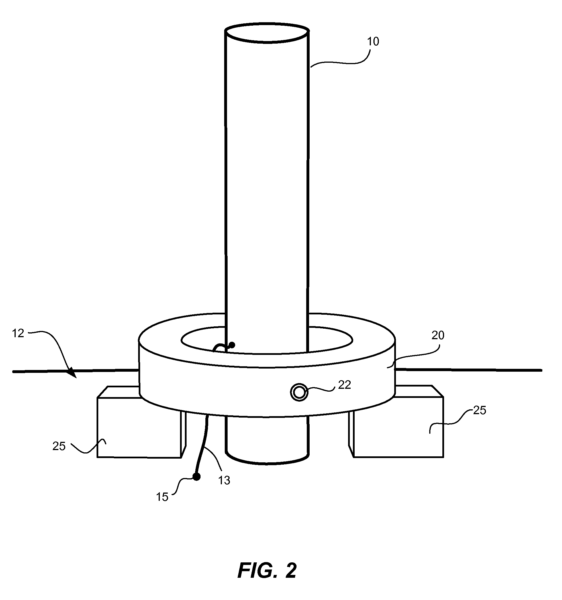
[0026]Due to limited real estate on deployment platforms, ships being an excellent example, collocated antenna systems are susceptible to electromagnetic interference to and from other antennas. Also, to be able to integrate additional antennas into these systems, antenna-to-antenna isolation must be managed to avoid the overloading of the RF front end stage of receivers. Typically with a shared antenna, a power divider can be attached to the antenna output port, causing the signal to be split between the various receivers (and / or transmitters). However, a power divider reduces the signal strength by as much as 3 dB or to the half power equivalent. For weak signals or for multi-split signals, this can result in signals that are below the detection threshold for the receiver.

[0027]There is a need to devise a way to convey signals from antennas without incurring the loss associated with a power divider, and also be able to modify existing antennas to have multiband capabilities. Magne...


PUM


Abstract

A multi-band antenna comprising a conductive structure and a plurality of current probes coupled around the conductive structure is disclosed. An existing antenna capable of generating H fields having a first signal line is converted into a multi-signal line antenna with increased frequency capabilities, by mounting a first current probe having a designated frequency range about a periphery of the existing antenna; coupling a second signal line to the first current probe; and performing at least one of transmitting and receiving via at least one of the first and second signal lines, wherein the mounting of the first current probe to the existing antenna improves a voltage standing wave ratio (VSWR) of the existing antenna and the second signal line operates as an independent signal line for signal reception/transmission within the designated frequency range.

Description

FEDERALLY-SPONSORED RESEARCH AND DEVELOPMENT[0001]This invention (Navy Case No. 098559) was developed with funds from the United States Department of the Navy. Licensing inquiries may be directed to the Office of Research and Technical Applications, Space and Naval Warfare Systems Center, San Diego, Code 72120, San Diego, Calif., 92152; voice 619-553-2778; email T2@spawar.navy.mil.FIELD OF THE INVENTION[0002]This disclosure relates to communication systems. More particularly, this disclosure relates to systems and methods for providing multiband signal capabilities for an antenna.BACKGROUND OF THE INVENTION[0003]With increasing numbers of wireless communications systems available today, more and more antennas are required to support them. In many situations the available real estate limits the number of additional antennas that may be added to a site. For example, the area available on building rooftops, and exterior surfaces of automobiles, aircraft, and vessels, which often serve ...

Claims


Application Information

Patent Timeline
Patent Type & Authority Patents(United States)
IPC IPC(8): H01Q1/00H01Q1/32H01Q9/00H01Q9/16
CPCH01Q5/40H01Q5/35H01Q9/30
Inventor TAM, DANIEL W. S.
Owner THE UNITED STATES OF AMERICA AS REPRESENTED BY THE SECRETARY OF THE NAVY
Why Eureka
Try Eureka