Battery charging circuit

A battery charging and circuit technology, applied to battery circuit devices, circuit devices, collectors, etc., can solve problems such as heat generation, current input value cannot be changed, energy loss, etc., to protect battery life, high frequency, reduce input The effect of current

Inactive Publication Date: 2016-05-04
NINGBO AMBON EMERGENCY PROD
View PDF0 Cites 2 Cited by
  • Summary
  • Abstract
  • Description
  • Claims
  • Application Information

AI Technical Summary

Problems solved by technology

[0003] Nowadays, the battery will be charged by a charging circuit. There are two existing charging circuits. The first is a diode charging circuit. Because the diode itself will generate a voltage above 0.3V, it will cause a large energy loss when charging the battery with a large current. This leads to serious heating, and the input current will not change and has been charged with a large current; while the second type charges two CMOS tubes, this circuit also has the disadvantage that the current input value cannot be changed.

Method used


Image

  • Battery charging circuit

Examples


Embodiment Construction

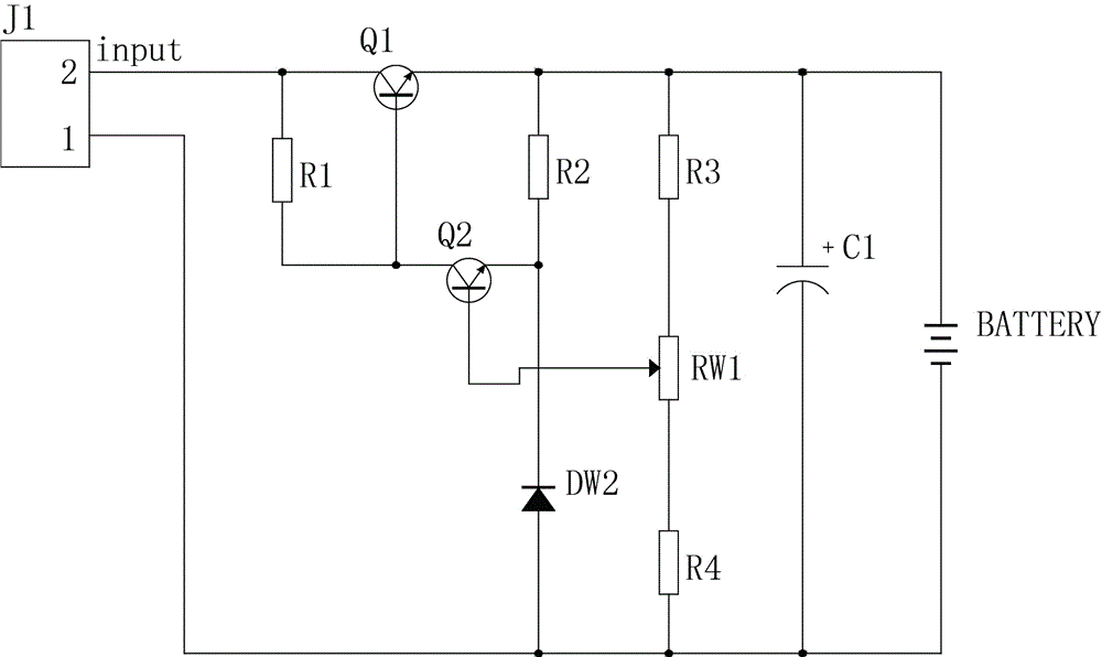
[0009] The present invention will be further described below in conjunction with the accompanying drawings and specific embodiments.

[0010] See figure 1 , a battery charging circuit, comprising an input terminal J1, a first transistor Q1, a second transistor Q2, a first resistor R1, a second resistor R2, a third resistor R3, a fourth resistor R4, a diode DW2, a battery , a capacitor C1, and an adjustable resistor RW1; the input end of the input end J1 is connected to one end of the first resistor R1, and the input end of the input end J1 is also connected to the collector of the first triode Q1, and the first The other end of a resistor R1 is connected to the base of the first transistor Q1, the emitter of the first transistor Q1 is connected to one end of the second resistor R2, and the base of the first transistor Q1 is also connected to the first The collector of the second transistor Q2, the emitter of the second transistor Q2 is connected to the other end of the second...


PUM


Abstract

The invention discloses a battery charging circuit. An input current can be reduced at a high voltage by comparing a group of bleeder circuits with a fixed voltage through a triode and controlling an input by a high-current triode, so that the role in protecting the lifetime of a battery is put into play.

Description

technical field [0001] The invention relates to the field of charging circuits, and specifically designs a battery charging circuit. Background technique [0002] After the battery is discharged, use direct current to pass through the battery in the opposite direction to the discharge current to restore its working ability. This process is called battery charging; there are a lot of sulfuric acid and other ionizable solutions in the battery. When the power is plugged in, the current will pass through the battery. The lead plate inside (some batteries are not lead) ionizes the solution, which converts electrical energy into chemical energy; if it is used, the solution is converted into electrical energy and sent through the electrodes; while the battery is charged, the positive terminal of the battery is connected to the positive terminal of the power supply, The negative pole of the battery is connected to the negative pole of the power supply, and the voltage of the chargin...

Claims


Application Information

Patent Timeline
Patent Type & Authority Applications(China)
IPC IPC(8): H02J7/00
CPCH02J7/0072
Inventor 何建芬徐乃军
Owner NINGBO AMBON EMERGENCY PROD
Why Eureka
Try Eureka