Board-to-board connector

a technology of connectors and coaxial connectors, applied in the direction of fixed connections, cross-talk/noise/interference reduction, printed circuit manufacturing, etc., can solve the problems of increasing the cost of miniature coaxial connectors used for board-to-board connections, increasing the cost of manufacturing, and reducing the cost of insertion, so as to reduce the cost, reduce the cost, and improve the effect of electrical and mechanical performan

Inactive Publication Date: 2006-08-08
REVEAL IMAGING
View PDF15 Cites 1 Cited by
  • Summary
  • Abstract
  • Description
  • Claims
  • Application Information

AI Technical Summary

Benefits of technology

[0007]The present invention provides a unique connector and method of interconnecting cooperating circuit boards, allowing the transfer of high frequency signals from one circuit board to the other circuit board, while maintaining good electrical and mechanical performance, at a significantly reduced cost. High frequency signals can now be transferred with low insertion loss and low return loss using the affordable connector of the present invention. Low cost materials are used for a body, a central conductor, and a ground connection. Standard surface-mount attachment techniques for printed wiring boards can also be used. Board-to-board vertical alignment tolerances can be compensated, and the frequency performance of board-to-board connections can be extended. The connector can be scaled to match mating boards of different dielectric constants or heights.
[0011]In yet another aspect of the present invention, a flexible conductive material can engage the conductive pin on the same surface as the flexible conductive material engaging the arcuate contact member. This additional flexible conductive material can be adapted for passing signals from the conductive pin through the flexible conductive material into the circuit board. In this manner, a compliant biasing element, for example, the fuzz button, does not have to be used.

Problems solved by technology

Unfortunately, board-to-board connectors with good performance become more difficult to fabricate and are more expensive as the frequencies being transferred between the different boards increase.
As a result, miniature coaxial connectors used for board-to-board connections are relatively expensive and do not have adequate ground connections for high frequency operation and transfer.

Method used


Image

  • Board-to-board connector
  • Board-to-board connector
  • Board-to-board connector

Examples


Embodiment Construction

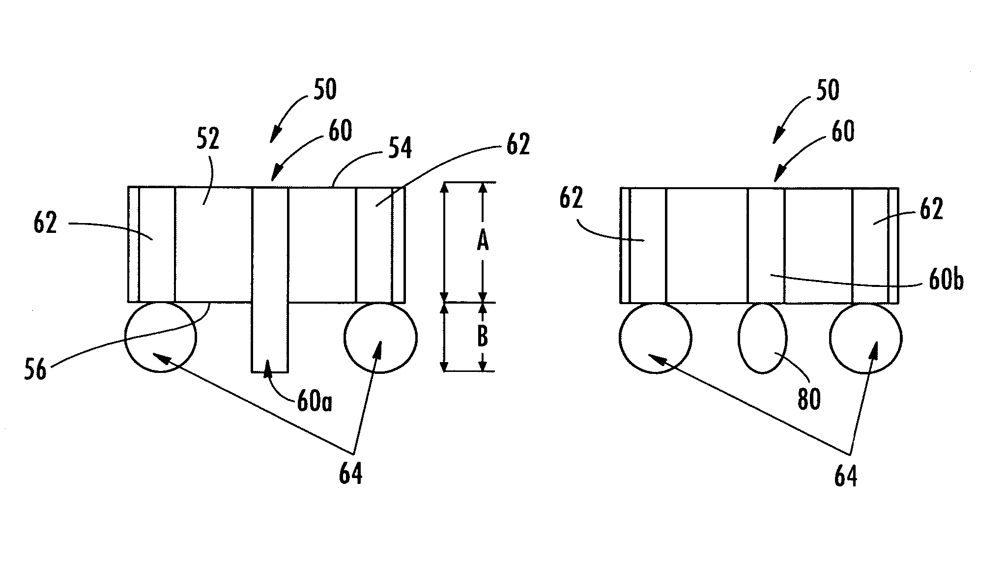
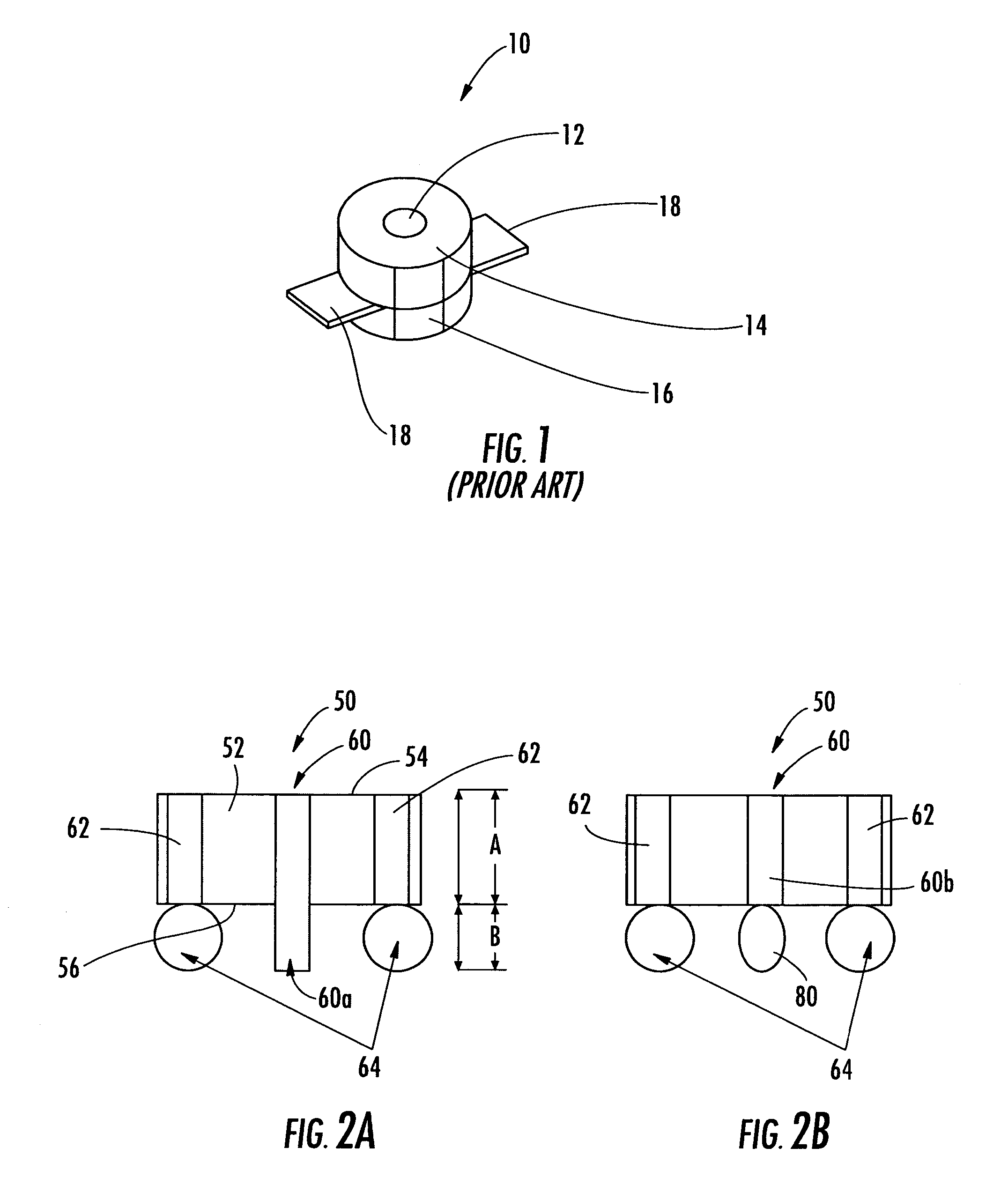
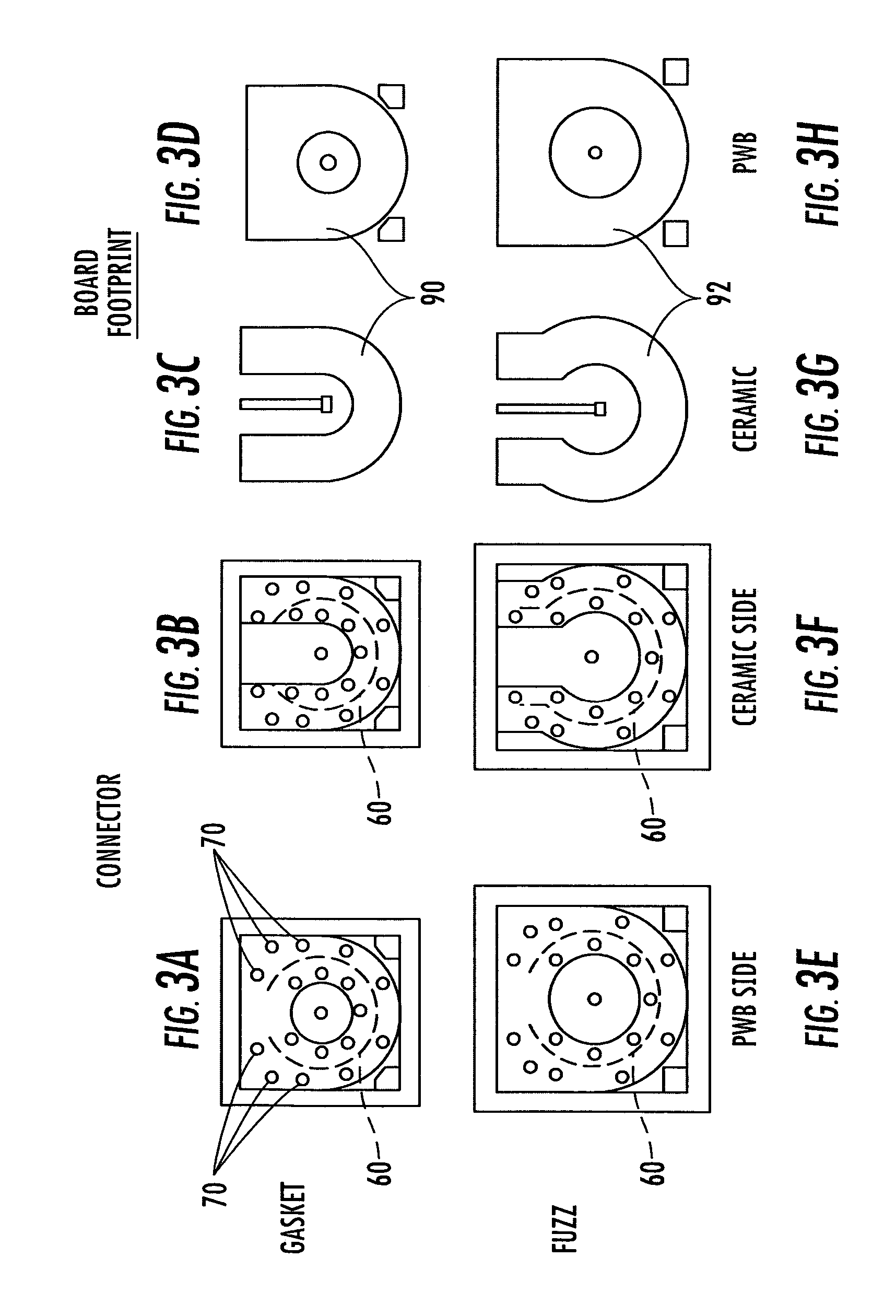
[0020]The present invention will now be described more fully hereinafter with reference to the accompanying drawings, in which preferred embodiments of the invention are shown. This invention may, however, be embodied in many different forms and should not be construed as limited to the embodiments set forth herein. Rather, these embodiments are provided so that this disclosure will be thorough and complete, and will fully convey the scope of the invention to those skilled in the art. Like numbers refer to like elements throughout.

[0021]The present invention provides a novel and unobvious connector and method of connecting cooperating circuit boards and transferring high frequency signals from one circuit board to another circuit board, while maintaining good electrical and mechanical performance, at a significantly reduced cost. Using the connector of the present invention, high frequency signals can be transferred with low insertion loss and low return loss. Lower cost materials a...


PUM


Abstract

The disclosed connector and method transfers high frequency signals from one circuit board to another circuit board, while maintaining good electrical and mechanical performance, at a significantly reduced cost. The connector includes a body member and a conductive pin extending through a center portion of the body member to opposing planar surfaces. An arcuate contact member is positioned within the body member and circumferential to at least a portion of the conductive pin. A flexible conductive material is positioned on an opposing surface and engages the arcuate contact member such that the connector can be positioned between cooperating circuit boards, allowing the conductive pin and arcuate contact member to operatively engage the circuit boards for passing signals therebetween.

Description

RELATED APPLICATION[0001]This application is based upon prior filed copending provisional application Ser. No. 60 / 528,025 filed Dec. 9, 2003.FIELD OF THE INVENTION[0002]This invention relates to a connector and method for connecting cooperating circuit boards, and more particularly, this invention relates to a connector and method for connecting a pair of cooperating circuit boards and passing high frequency signals therebetween.BACKGROUND OF THE INVENTION[0003]Most high frequency radio modules, for example, a high frequency radio transceiver module, use several circuit boards on which electronic components are mounted to reduce module costs or optimize module size. These module costs can be further reduced by mounting only high frequency components on those boards that require more expensive circuit components and materials, for example, by mounting microwave monolithic integrated circuit (MMIC) chips on a ceramic board, and forming a radio frequency (RF) transceiver board. The les...

Claims


Application Information

Patent Timeline
Patent Type & Authority Patents(United States)
IPC IPC(8): H01R12/00H05K1/02H05K3/32H05K3/36
CPCH01R12/62H01R12/714H01R12/52H05K1/0219H05K3/368H05K3/325
Inventor HUBERT, JOHN
Owner REVEAL IMAGING
Why Eureka
Try Eureka