Method for controlling an automatic multi-step shift transmission

Active Publication Date: 2012-04-24
ZF FRIEDRICHSHAFEN AG
View PDF15 Cites 8 Cited by
  • Summary
  • Abstract
  • Description
  • Claims
  • Application Information

AI Technical Summary

Benefits of technology

[0009]Accordingly, the purpose of the present invention is to indicate a method for controlling an automatic multi-step shift transmission of the type mentioned at the start, by virtue of

Problems solved by technology

The disadvantage of an upshift that takes place only after moving onto level ground or after the transition to traction operation, is that the momentum of the motor vehicle, i.e. the driving force due to the slope, is used only insufficiently when moving off the slope to propel the motor vehicle while it is moving off the slope and at the beginning of the subseq

Method used


Image

  • Method for controlling an automatic multi-step shift transmission
  • Method for controlling an automatic multi-step shift transmission
  • Method for controlling an automatic multi-step shift transmission

Examples


Embodiment Construction

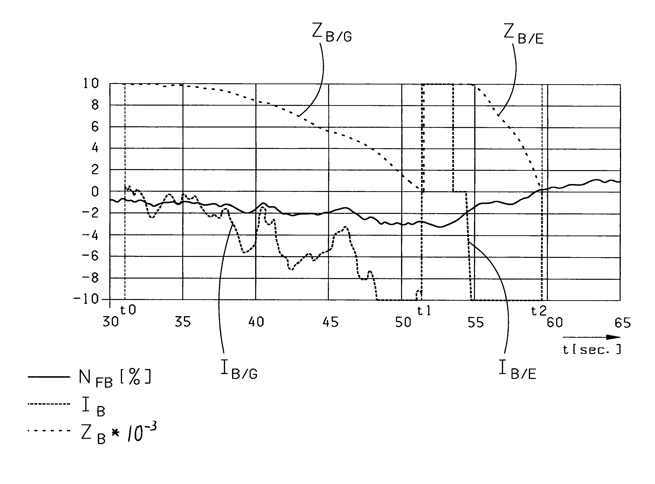
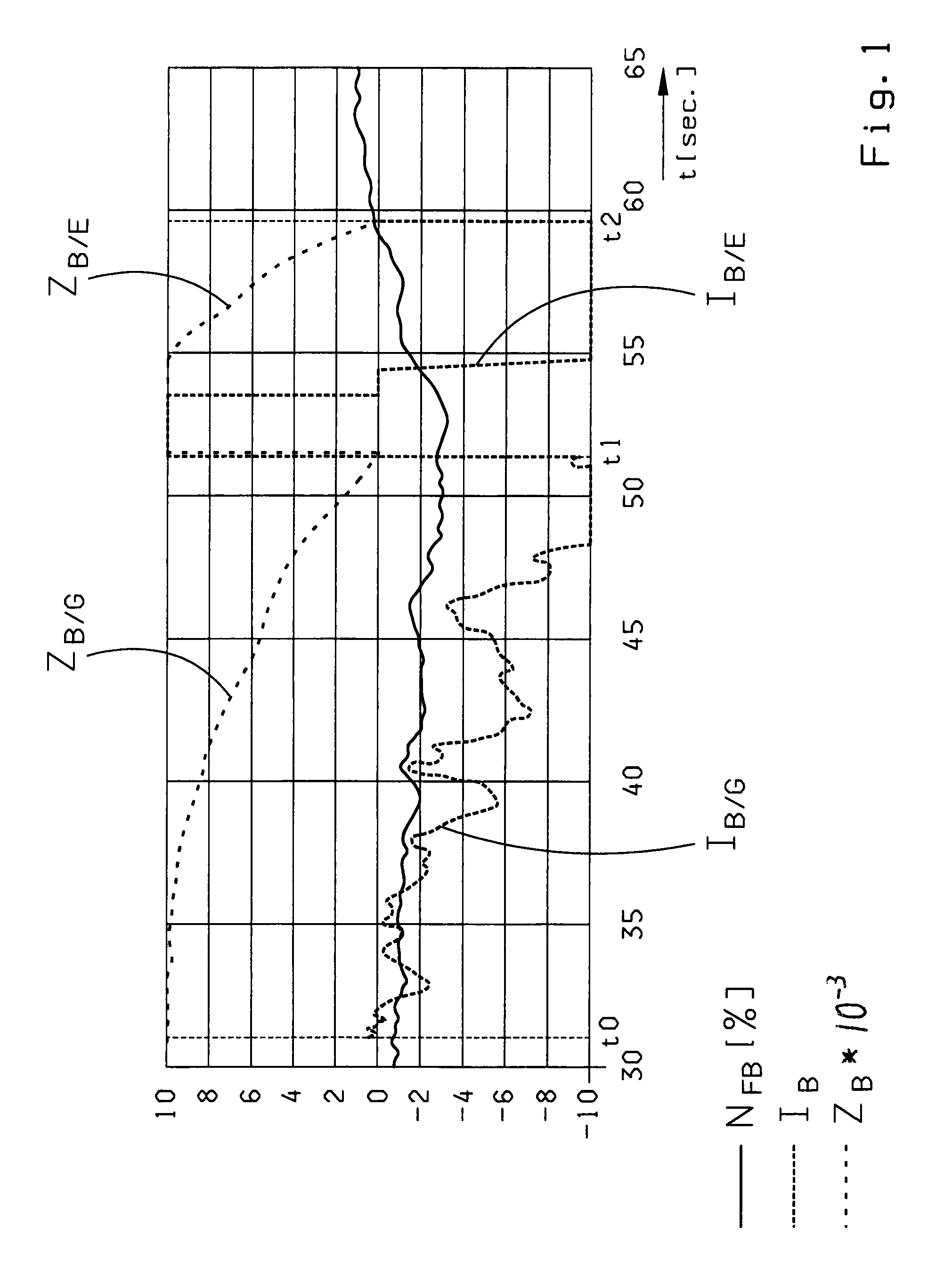
[0051]FIG. 1 shows the time variations determined during the driving operation of a motor vehicle, of a road inclination NFB preferably calculated from the current drag torque MMDBr of a permanent brake, the current driving speed vF and the current driving acceleration aF using the movement equation, that of an observation counter ZB, and that of a counter increment IB. The observation counter ZB and the counter increment IB are in each case part of a first part-function and a second part-function of a recognition function for detecting a downhill run-out.

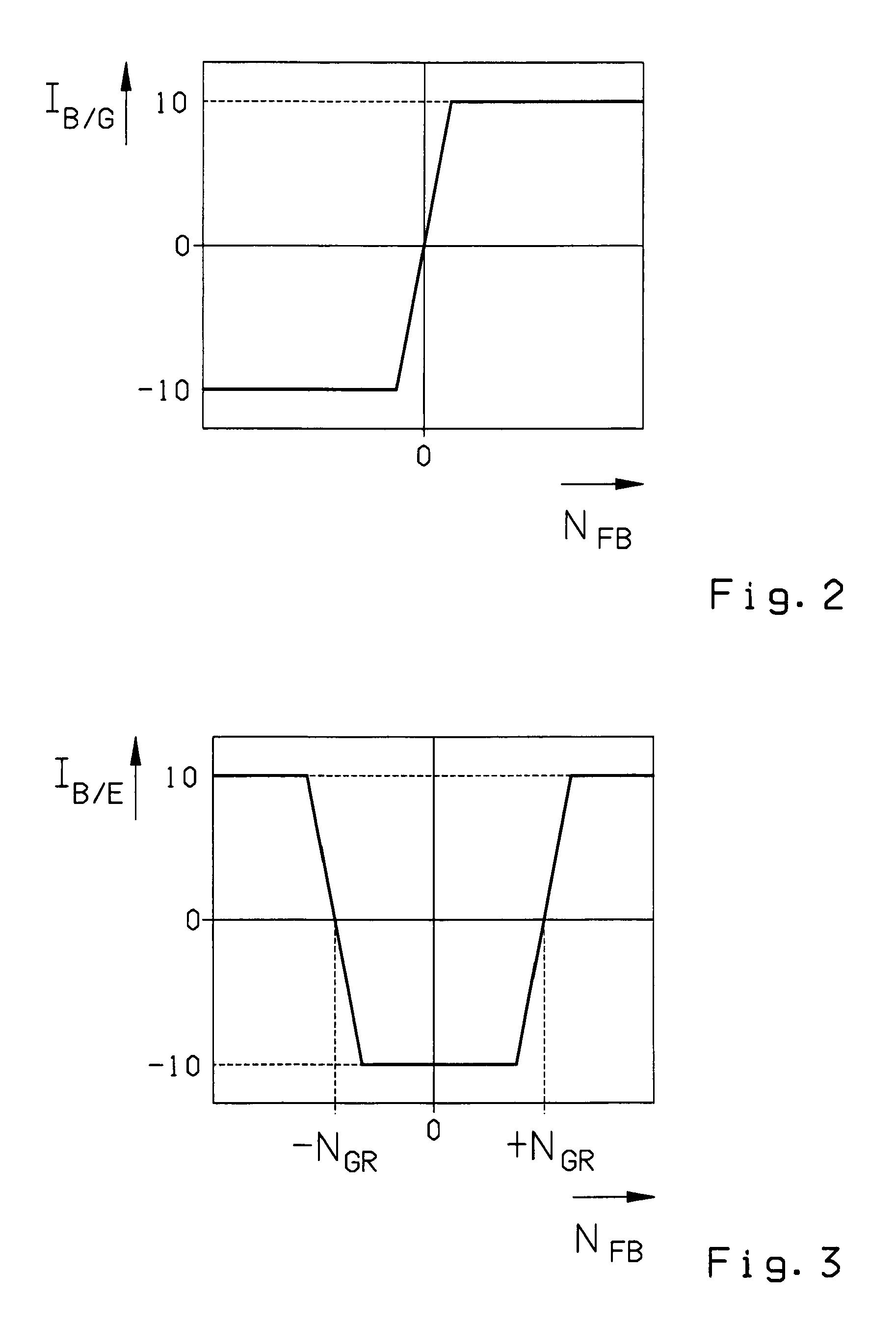
[0052]The first part-function serves to detect a downhill gradient (NFB0 at which, for example, the starting conditions, namely a current downhill road gradient (NFBMB / G begins with a positive initial value ZB / G—0=103 and is varied additively in steps, in the present case of 0.1 seconds, by the counter increment IB / G which is determined as a function of the road inclination NFB and can adopt values between −10 and +10.

[0053]The fun...


PUM


Abstract

A method of controlling an automatic transmission arranged in a vehicle between a drive motor and an axle drive of a drive axle or a transfer box such that the current road inclination is determined and, after driving onto a downhill stretch of road, to increase a braking action of the drive motor and/or a permanent brake, a shift to a lower gear is carried out and after a transition to a traction operation or after driving onto level ground, a shift to a higher gear is carried out. To improve transmission shifting behavior, when transitioning between a downhill stretch and level ground, it is provided that a function for detecting a downhill run-out is started and if a downhill run-out is detected, and a shift to a higher gear is carried out while still in a thrust operation before driving onto the level ground and/or before the transition to traction operation.

Description

[0001]This application is a National Stage completion of PCT / EP2008 / 062016 filed Sep. 11, 2008, which claims priority from German patent application serial no. 10 2007 044 434.8 filed Sep. 18, 2007.FIELD OF THE INVENTION[0002]The invention concerns a method for controlling an automatic multi-step shift transmission arranged in a drivetrain of a motor vehicle, such as a utility vehicle, in the force flow between a drive motor, which is an internal combustion engine, and an axle drive of a drive axle or a transfer box, in which method the current road inclination is determined, and after driving onto a downhill stretch, to increase the braking action of the drive motor and / or that of a permanent brake a shift is made to a lower gear, and at the latest after a transition to traction operation or after driving onto level ground a shift is made to a higher gear.BACKGROUND OF THE INVENTION[0003]In the case of a motor vehicle having an automated multi-step shift transmission such as an aut...

Claims


Application Information

Patent Timeline
IPC IPC(8): G06F7/00G06F19/00G06F17/00
CPCF16H61/0213F16H59/66F16H61/21F16H2061/0237F16H2059/663
Inventor WOLFGANG, WERNERWUERTHNER, MAIK
Owner ZF FRIEDRICHSHAFEN AG
Why Eureka
Try Eureka