Electric powered cart for moving loads

a technology of electric powered carts and moving loads, which is applied in the direction of electric propulsion mounting, transportation and packaging, battery/cell propulsion, etc., can solve the problem of limiting the ability to use conventional media to perform this function, and achieve the effect of low cost, easy assembly and installation, and low degree of technical complexity or sophistication

Active Publication Date: 2012-05-01
GM GLOBAL TECH OPERATIONS LLC
View PDF63 Cites 16 Cited by
  • Summary
  • Abstract
  • Description
  • Claims
  • Application Information

AI Technical Summary

Benefits of technology

[0006]The vehicle and its operating systems are assembled readily and installed easily on the cart's frame or vehicle's chassis at low cost and without a high degree of technical complexity or sophistication.
[0007]The truck provides a high level of capability and flexibility that surpasses that of alternative transportation techniques, and meets or exceeds safety specifications for a power assist device at a substantially lower cost that otherwise commercially available.
[0008]The truck is a relatively inexpensive device that assists production operators and material handling personnel to move loads of about one ton around a production plant.

Problems solved by technology

However, when the transported load is heavy, in the range of about 2000 pounds, ergonometric guidelines frequently limit the ability to use conventional media to perform this function without exceeding the guidelines.

Method used


Image

  • Electric powered cart for moving loads
  • Electric powered cart for moving loads
  • Electric powered cart for moving loads

Examples


Embodiment Construction

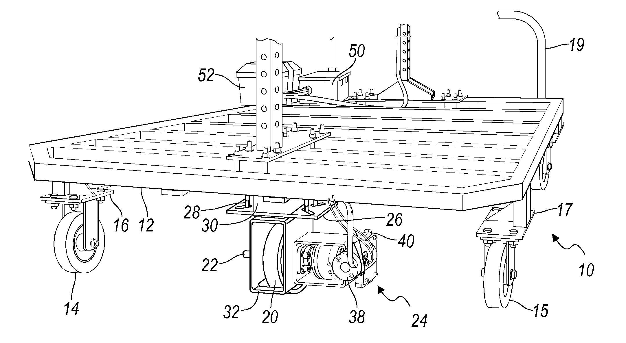
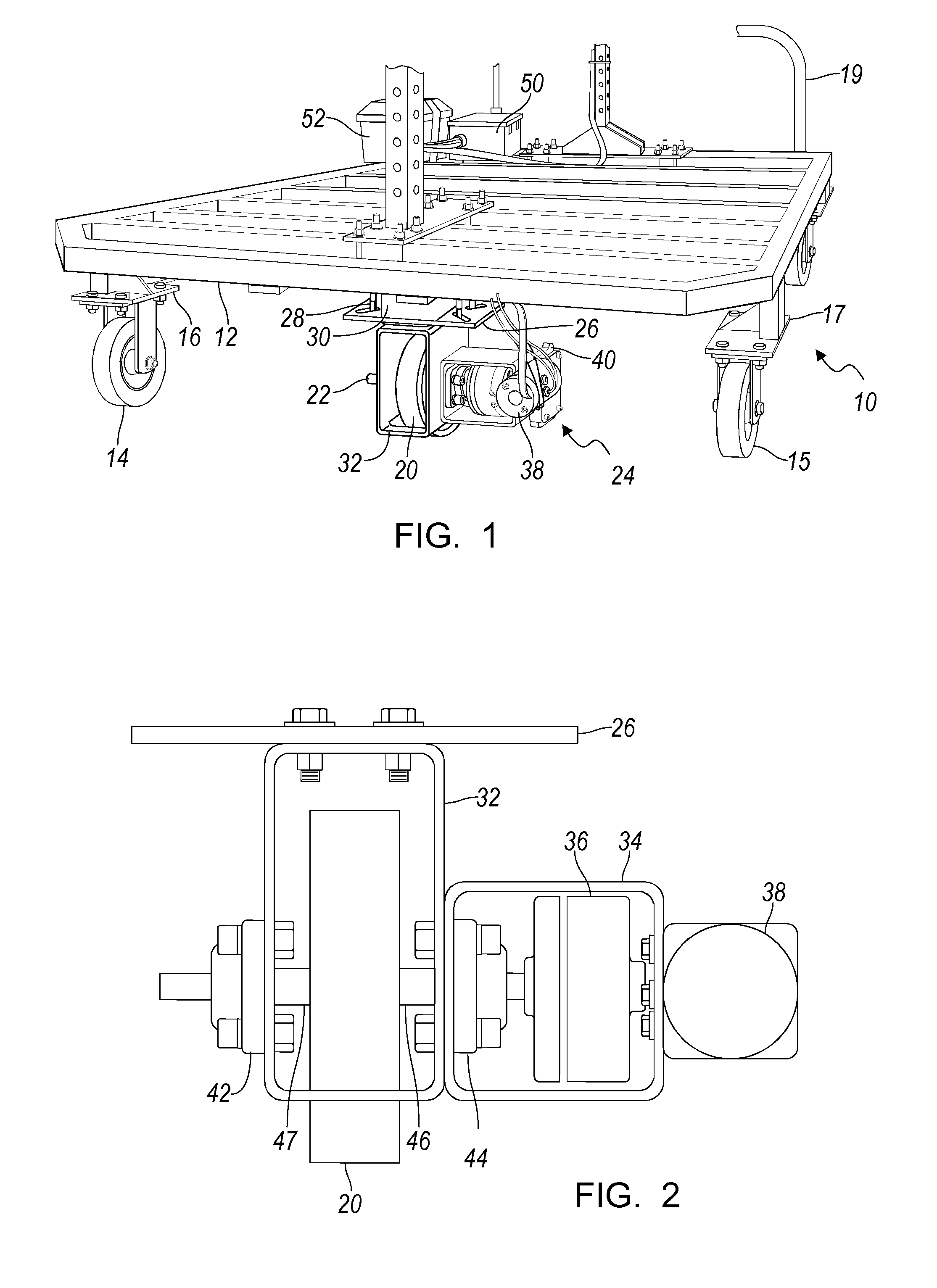
[0013]Referring now to the drawings, illustrated in FIG. 1 is a cart 10, which includes a rectangular welded frame 12 formed preferably of rolled or extruded members, each member having a closed cross section in the form of a rectangular, preferably square, tube. The frame 12 is supported on a first set of caster wheels 14, 15, each wheel bolted to a support 16, 17, respectively, which is located at a corner of the frame 12 and welded to the lower surface of the frame 12. A second set of wheels similarly mounted to the frame 12, but located at the opposite end of the frame 12, are on casters to facilitate steering the vehicle. A handle 19, secured to the end of the frame where the caster wheels are located, is used to apply a lateral steering force manually to the cart.

[0014]A single drive wheel 20, in traction contact with the floor is aligned with a central longitudinal axis of the frame 12, evenly spaced between wheels 14, 15. Drive wheel 20 is supported on a drive shaft 22, whos...


PUM


Abstract

A cart for moving loads includes a frame supported on wheels, a source of electric power supported on the frame, a drive system including a traction motor connected to the power source for driving a wheel secured to the frame and contacting ground, and a controller for adjusting a rotary direction of the drive wheel in response to selected states of an input to the controller.

Description

BACKGROUND OF INVENTION[0001]The present invention relates generally to an apparatus for transporting heavy loads on the floor of a factory or assembly plant. More particularly, the invention relates to a cart controlled by a vehicle operator and powered by onboard electric energy.[0002]Various techniques used to transport material and components between workstations on a factory floor include conveyors such as conventional belt conveyors, fork trucks and manned tuggers. However, when the transported load is heavy, in the range of about 2000 pounds, ergonometric guidelines frequently limit the ability to use conventional media to perform this function without exceeding the guidelines.[0003]A preferable technique would provide a vehicle that operates under electric power and is guided by a vehicle operator to transport relatively heavy loads along any undefined path. The vehicle or cart would produce no noxious exhaust gas. The onboard power source, electric storage batteries, would ...

Claims


Application Information

Patent Timeline
Patent Type & Authority Patents(United States)
IPC IPC(8): B60K1/00
CPCB60L11/18Y02T10/7005B60L50/60Y02T10/70
Inventor SCHEUERMAN, ROBERT J.MERKLE, WILLIAM O.GIRARD, STEPHEN C
Owner GM GLOBAL TECH OPERATIONS LLC
Why Eureka
Try Eureka