Switch and electronic device

a technology of electronic devices and switches, applied in the direction of tumbler/rocker switches, magnets, tumblers, etc., can solve the problems of data not being written, data being unable to be written, data being damaged, etc., and achieve the effect of high reliability

Active Publication Date: 2012-05-01
ORMON CORP
View PDF6 Cites 3 Cited by
  • Summary
  • Abstract
  • Description
  • Claims
  • Application Information

AI Technical Summary

Benefits of technology

[0007]One or more embodiments of the present invention may provide a highly reliable switch for maintaining a power supply ON state until the data processing in a device is completed even if an operating element is ON operated to operate the device to be used and then the operating element is manually OFF operated with the stopping of the operation, and automatically turning OFF the power supply after the data processing is completed, and an electronic device.
[0009]According to one or more embodiments of the present invention, the power supply switch mechanism is turned ON when the operating element is ON operated. Even if the power supply is OFF operated thereafter, the power supply switch mechanism does not turn OFF instantaneously to maintain the ON state until the signal of the power supply reset is inputted. That is, the power supply is automatically turned OFF after the processing data when the use of electronic device to be used is stopped is reliably stored in the hard disk and the data processing is completed, and hence the data can be reliably saved and highly reliable data management can be realized.
[0010]Because the biasing force of the return spring for biasing in the OFF direction is regulated so that the biasing force of the return spring is not applied on the operating element after the operating element is OFF operated once, the operating element can freely turn in a single body and spins around. Thus, even if the operating element is thereafter ON / OFF operated again, the re-ON / OFF operation force idles and the operation force from the operating element is not transmitted to the contact of the power supply switch mechanism. Therefore, after the operating element is OFF operated the first time, issues may not arise even if the operating element is thereafter ON / OFF operated again carelessly and excelling use of the data management can be achieved.
[0012]According to one or more embodiments of the present invention, a coil spring that has flexible bendability not only in the axial direction but also in the crossing direction can be used for the elastic body. A configuration of transmitting the turning force of the state holding member to the movable piece through the elastic body is adopted, and in particular, the elastic body has strong durability because elastic deformation suited for turning ON / OFF can be easily realized by repeatedly bending and inverting, so that a stable switch mechanism can be ensured.
[0014]According to the present operation, a compact arrangement configuration of the switch components can be realized by using a slider for linearly advancing and retreating the operation force from the operating element, and the switch components can be efficiently incorporated in the housing in a concentrated manner. The miniaturization of the switch thus can be achieved.

Problems solved by technology

Thus, if the user OFF operates the operating element while data is being written to the hard disk, the power supply is turned OFF without protecting the data to be stored, and hence abnormality occurs such as the data cannot be written or the hard disk main body may break.

Method used


Image

  • Switch and electronic device
  • Switch and electronic device
  • Switch and electronic device

Examples


first embodiment

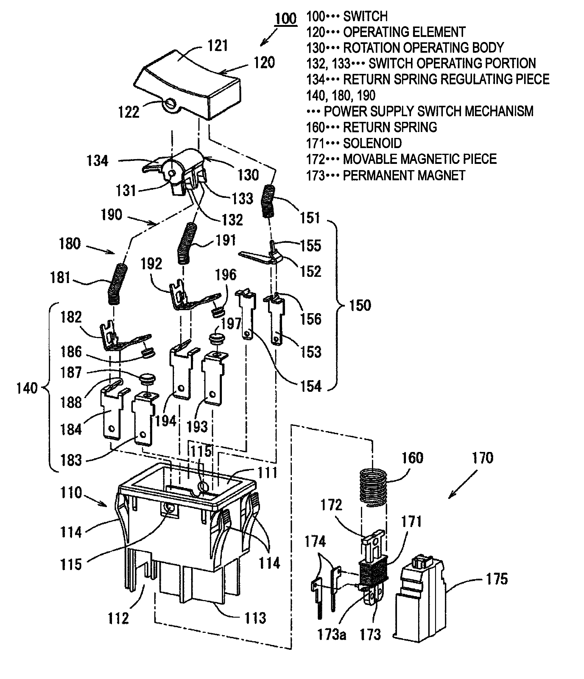
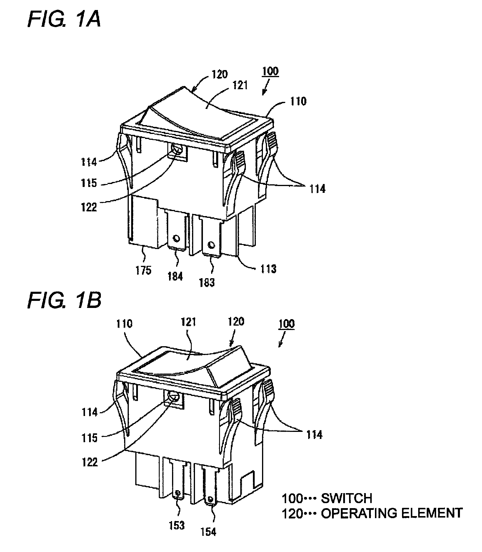
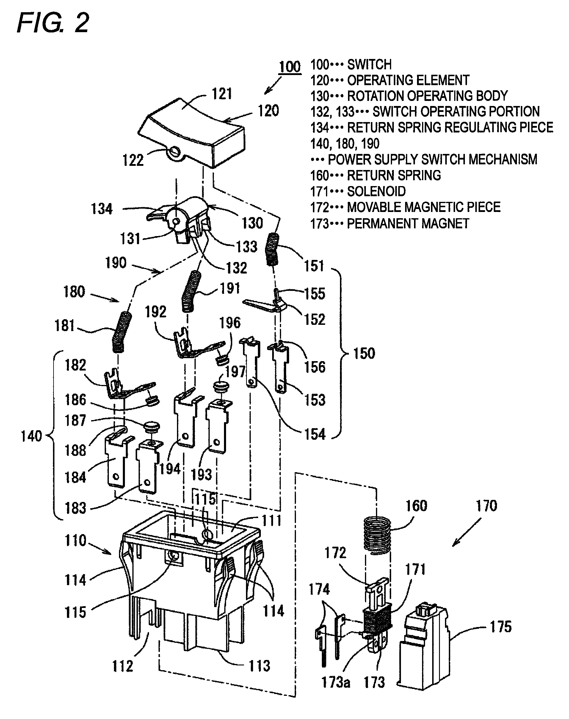
[0035]The drawings show a switch with a reset function, where FIG. 1A shows a perspective view of an outer appearance of a switch 100 seen from one side, and FIG. 1B shows a perspective view of the outer appearance of the switch 100 seen from the other side. FIG. 2 shows an exploded perspective view of the switch 100 seen from a diagonally upper side, and FIG. 3 shows an exploded perspective view of the switch 100 seen from a diagonally lower side.

[0036]The switch 100 having the reset function is configured to incorporate an operating element 120, a rotation operating body 130, a power supply switch mechanism 140, a signal switch mechanism 150, a return spring 160, and a power supply reset mechanism 170 in a housing 110.

[0037]The housing 110 has a box shape with the upper surface opened, where a recess shaped hollow portion 111 for incorporating the components 130, 140, 150, 160 described above is provided on the upper side, and a bottom attachment portion 112 and a terminal partiti...

second embodiment

[0089]The drawings show a switch 200 having a reset function. FIG. 9A shows a perspective view of the outer appearance of the switch 200 seen from one side and FIG. 9B shows a perspective view of the outer appearance of the switch 200 seen from the other side. FIG. 10 shows an exploded perspective view of the switch 200 seen from one side, and FIG. 11 shows an exploded perspective view of the switch 200 seen from the other side.

[0090]The switch 200 having the reset function is configured to incorporate an operating element 220, a slider 230, a power supply switch mechanism 240, a signal switch mechanism 250, a return spring 260, and a power supply reset mechanism 270 in a housing 210.

[0091]The housing 210 has a box shape with the upper surface opened, where a recess shaped hollow portion 211 for incorporating the components 230, 240, 250, 260 described above is provided on the upper side, and the bottom side is opened to the lower side to include a bottom attachment opening 212 and ...


PUM


Abstract

A switch and an electronic device maintain a power supply ON state until data processing is completed, and automatically turn OFF the power supply after the data processing is completed. The switch includes a rotation operating body that does not receive an operation force from an operating element when OFF operated is arranged inside the operating element. The rotation operating body includes a switch operating portion for turning ON a power supply switch mechanism and a return spring regulating piece for biasing a return spring in an anti-biasing direction. A regulating state of the return spring regulated by the return spring regulating piece is held, where the ON state of the power supply switch mechanism is held with a permanent magnet, and the ON state of the power supply switch mechanism is released by applying a release force on the permanent magnet when the power supply is reset.

Description

CROSS-REFERENCE TO RELATED APPLICATIONS[0001]The present application claims priority from Japanese Patent Application No. 2010-168848, filed Jul. 28, 2010. The contents of both priority applications are hereby incorporated by reference in their entirety.BACKGROUND OF THE INVENTION[0002]1. Technical Field[0003]One or more embodiments of the present invention relate to a switch having a reset function of reliably storing processing data in a hard disk and turning OFF a power supply after data processing is completed when the use of a electronic device including a control unit such as a copy machine or a personal computer is stopped, and an electronic device.[0004]2. Related Art[0005]Generally, in a switch having data protecting performance, contacts included so as to be in contact with or separate from each other in the switch are brought into contact to turn ON the power supply of the switch when the user manually operates an operating element operated in a see-saw manner. The operat...

Claims


Application Information

Patent Timeline
Patent Type & Authority Patents(United States)
IPC IPC(8): H01H9/00
CPCH01H3/20H01H7/00H01H23/22H01H23/205H01H9/20
Inventor KIYONO, YASUHIRONARUO, TOSHIHIRO
Owner ORMON CORP
Why Eureka
Try Eureka