Supercharge Your Innovation With Domain-Expert AI Agents!

Light modulator for representing complex-valued data

a technology of complex value and light modulator, applied in the field of light modulator for representing complex value information, can solve the problems of complicated encoding methods, difficult adjustment, irrelevant disadvantages, etc., and achieve the effect of widening the range of angle-specific optical retardation among adjacent pixels or pixel groups

Active Publication Date: 2012-05-01
SEEREAL TECHNOLOGIES
View PDF9 Cites 0 Cited by
  • Summary
  • Abstract
  • Description
  • Claims
  • Application Information

AI Technical Summary

Benefits of technology

[0018]It is therefore the object of the present invention to provide a light modulator for representing complex-valued information, which is designed such that a disturbing, angle-specific optical retardation among adjacent pixels or pixel groups is widely prevented.
[0020]The light modulator for representing complex-valued information comprises an encoding surface with an arrangement of pixels, whose phase can be controlled, where according to the characterising clause of claim 1 at least one given pixel of each pixel group of adjacent pixels of the encoding surface is assigned with a certain structured retardation layer which causes an angle-specific change in the optical path length of an exiting bundle of rays, where the layer thickness of the retardation layer is designed such that the change in the optical path length through the retardation layer counteracts the angle-specific change in the retardation among individual pixels of a pixel group and compensates the angle-specific change in the retardation at least partly or even entirely.
[0045]The retardation layer which is disposed behind the pixels causes light beams with an oblique angle of incidence to cover different optical path lengths OW for the angle α through the pixels which are separated by one pixel such that the retardation to the adjacent pixels is compensated partly or even entirely.
[0052]The retardation layers can also be composed of multiple sub-layers which are disposed one above another. These sub-layers can be connected with interface layers, for example adhesive layers. Such a layer stack can for example serve to simplify the manufacturing process.

Problems solved by technology

However, this has the disadvantage that a difficult adjustment is required because the pixel structure of the two light modulators must be congruent.
This disadvantage will be irrelevant if a complex number is represented by a group of multiple pixels on the same light modulator.
However, this involves complicated encoding methods which are associated with an iterative computation of the complex-valued code.
However, this only applies if there is no further optical retardation except the computed one of the light beams between the two pixels.
However, on the one hand, if light is diffracted at the adjacent pixels of a pixel group then an angle-specific optical retardation occurs, which causes errors in the hologram reconstruction.
However, this causes an increased computational load, which is for example disturbing in a real-time computation of holograms.
Due to pixel dimensions of conventional light modulators, another problem in display holography is the very small useable diffraction angle, which greatly limits either the extent or the visibility region of a holographically reconstructed scene.
This disadvantage is not compensated by avoiding the vertical parallax to be encoded, i.e. if only the horizontal parallax is holographically encoded.
If an HPO encoding method and a light modulator with a two-dimensional arrangement of pixels are used, and if there are no mutually independent values which are written to each row of the light modulator, but always groups of multiple rows, there will be the possibility to widen the usable horizontal diffraction angle at the cost of a loss of vertical resolution.
In HPO holograms, a dependence of the hologram reconstruction on the vertical diffraction angle is not desired.
However, if a group of rows of a light modulator is coherently illuminated, this will cause in the vertical direction an undesired, angle-specific retardation among the individual rows, while in the horizontal direction the retardation among adjacent columns is required for the reconstruction, because in a phase encoding method it comprises the information about the object to be reconstructed.
In either case, for the phase encoding method with multiple pixels for representing a complex number, and for the coherent combination of multiple HPO-encoded light modulator rows, the same problem occurs: on the one hand, a disturbing, angle-specific optical retardation occurs between the groups of few adjacent pixels, while on the other hand the optical retardation to other pixels or pixel groups, which is likewise generated, is either insignificant or even required for the hologram reconstruction.

Method used


Image

  • Light modulator for representing complex-valued data
  • Light modulator for representing complex-valued data
  • Light modulator for representing complex-valued data

Examples


Embodiment Construction

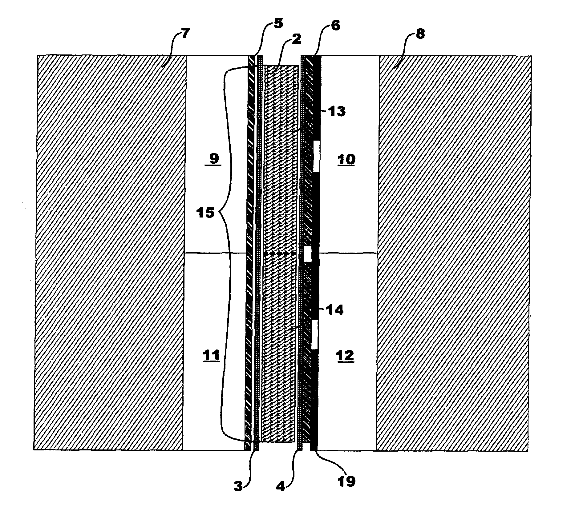
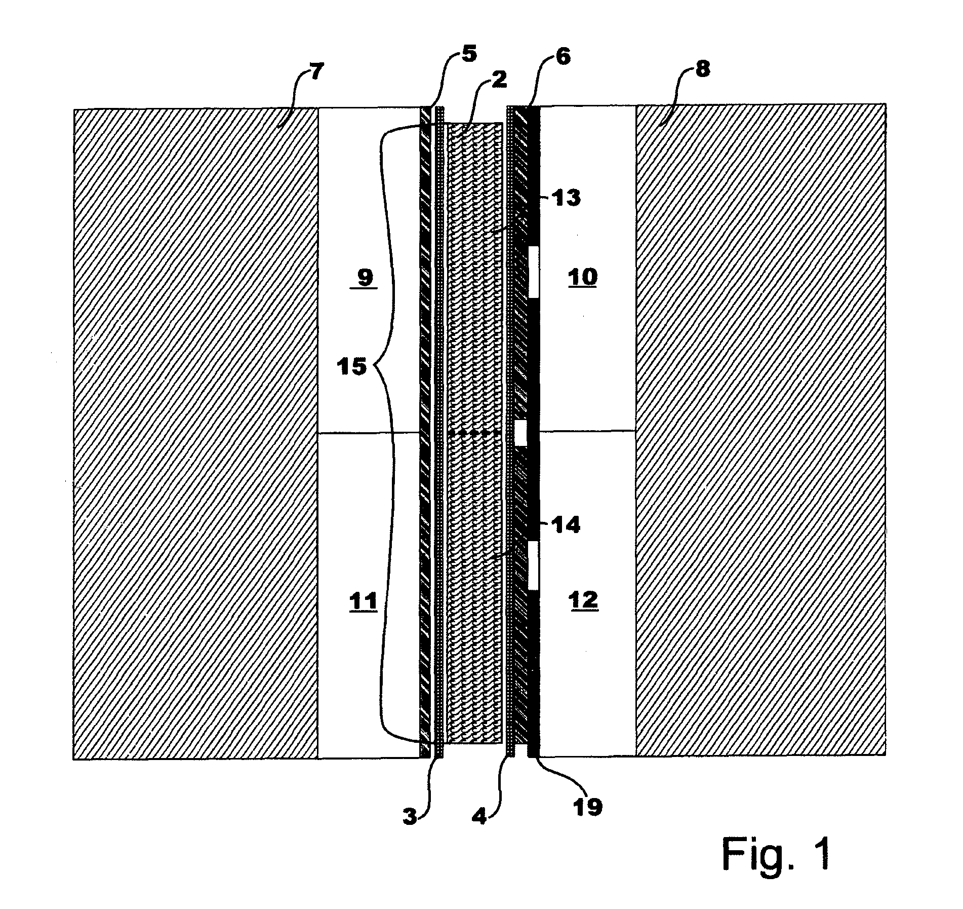
[0068]FIG. 1 shows schematically a light modulator 1 according to this invention, comprising:[0069]A liquid crystal layer 2,[0070]An orientation layer 3, 4 which is disposed on the two sides of the liquid crystal layer 2,[0071]An electrode layer 5, 6 which is disposed on the two free sides, and[0072]A glass plate 7, 8 which is disposed on the two free sides,

Thus providing a two-dimensional arrangement of pixels 13, 14, whose transmissive amplitude or phase can be controlled with the help of potentials which are supplied to the electrode layers 5, 6.

[0073]According to the present invention, a structured retardation layer 9, 10, 11, 12 is disposed at least between one of the electrode layers 5, 6 and the glass plate 7, 8 which lies opposite the electrode layer 5, 6, said structured retardation layer causing an angle-specific change in the optical path length of an incident bundle of rays having linear polarisation, where the thickness of the retardation layer 9, 10, 11, 12 is dimensio...


PUM


Abstract

A light modulator is disclosed for representing complex-valued data, comprising an encoding area that has an arrangement of pixels, the phase of which can be controlled. This largely avoids an interfering optical path difference between adjacent pixels or pixel groups when a complex value is encoded in several adjacent phase pixels of the encoding area, the optical path difference varying according to the angle. One respective specific structured delaying layer, which causes the optical path of an incident linearly polarized beam to change according to the angle, is associated with at least one predefined pixel of a group of adjacent pixels of the encoding area. The thickness of the delaying layer is designed such that the modification of the optical path caused by the delaying layer runs in the opposite direction from the angle-related modification of the optical path difference between individual pixels of the pixel group.

Description

CROSS REFERENCE TO RELATED APPLICATIONS[0001]This application claims the priority of PCT / EP2008 / 055211, filed on Apr. 29, 2008, which claims priority to German Application No. 10 2007 021774.0, filed Apr. 30, 2007, the entire contents of which are hereby incorporated in total by reference.BACKGROUND OF THE INVENTION[0002]The present invention relates to a light modulator for representing complex-valued information, comprising an encoding surface with an arrangement of pixels whose transmissive or reflective phase shift is controllable.[0003]The computation of computer-generated holograms and similar diffractive structures for encoding on pixelated light modulators generally provides complex-valued information, i.e. numbers, with a real part and an imaginary part, said information being written in the form of amplitude or phase information to the light modulator with a discrete pixel structure and being reconstructed with the help of sufficiently coherent illumination.[0004]The light...

Claims


Application Information

Patent Timeline
IPC IPC(8): G02F1/07
CPCG02F1/133632G03H1/2294G02F2413/09G03H1/02G03H2001/0858G03H2223/13G03H2225/32G03H2225/55G03H2240/13G03H2225/33G02F1/133631G02F1/13363
Inventor KROLL, BOSCHWERDTNER, ARMINLEISTER, NORBERT
Owner SEEREAL TECHNOLOGIES
Features
  • R&D
  • Intellectual Property
  • Life Sciences
  • Materials
  • Tech Scout
  • Unparalleled Data Quality
  • Higher Quality Content
  • 60% Fewer Hallucinations
Learn More