System and method for road angle estimation

a technology of system and method, applied in the direction of process and machine control, instruments, digital computer details, etc., can solve the problems of inapplicability, inability to estimate two road angles simultaneously, and inability to accurately estimate two road angles

Inactive Publication Date: 2012-05-01
NAT CHIAO TUNG UNIV
View PDF7 Cites 68 Cited by
  • Summary
  • Abstract
  • Description
  • Claims
  • Application Information

AI Technical Summary

Benefits of technology

[0012]Therefore, the object of the present invention is to provide a system and method for road angle estimation that can overcome the aforesaid drawbacks associated with the prior art.

Problems solved by technology

1. Many existing techniques utilize empirical formulas to estimate road angle. However, such methods are imprecise, and are not applicable to a road surface having road angles that vary rapidly and frequently.
2. Existing techniques estimate two road angles separately, and are unable to estimate two road angles simultaneously.
3. Current techniques require the use of four or more sensors for road angle estimation.
4. Road angles defined by conventional techniques are relative to the front of the vehicle, and such a manner of defining road angles is different from traditional Euler angles. Hence, even if two angle values are obtained, road conditions on a global (or terrestrial) reference frame cannot be described sufficiently rapidly.

Method used


Image

  • System and method for road angle estimation
  • System and method for road angle estimation
  • System and method for road angle estimation

Examples


Embodiment Construction

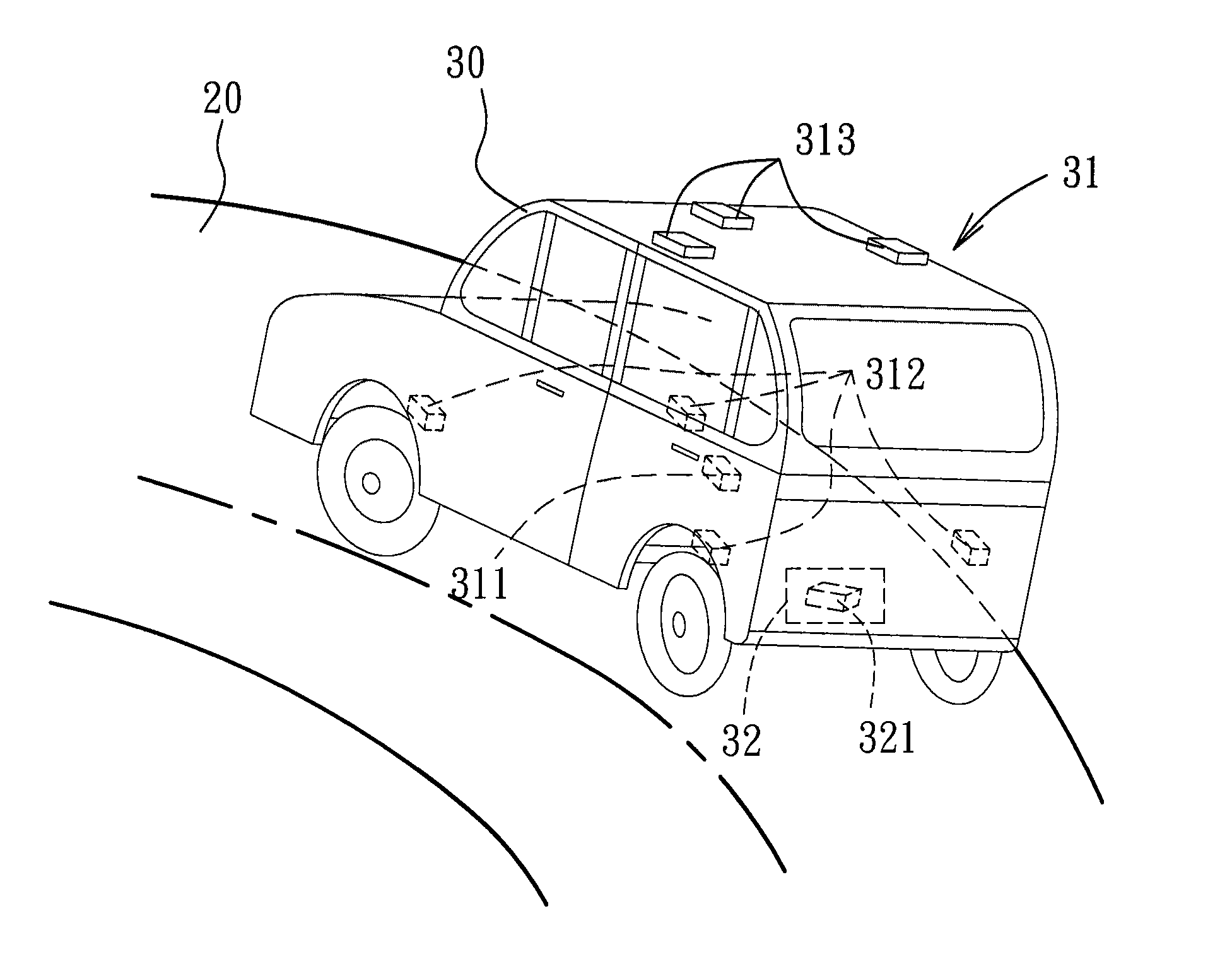
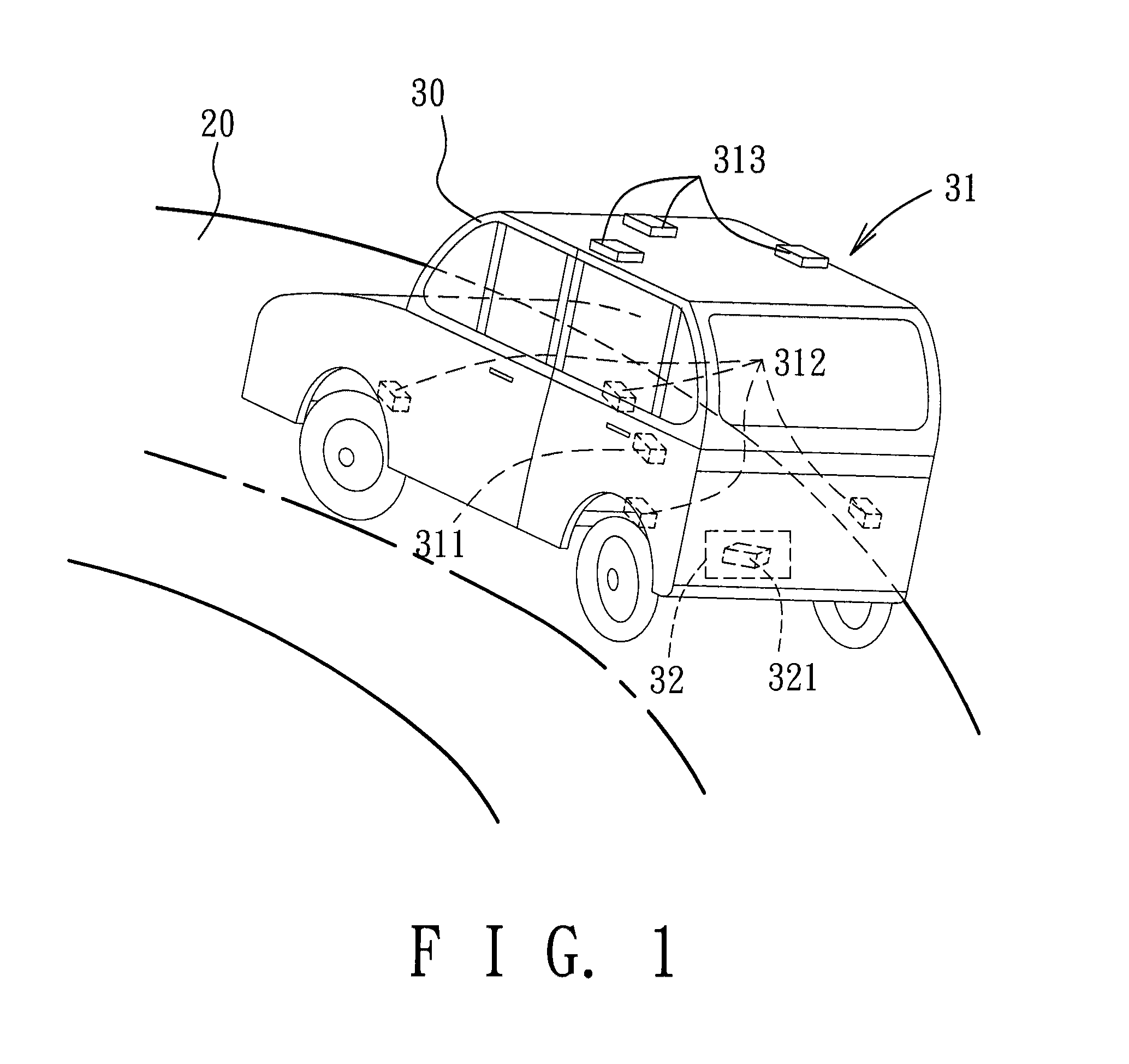
[0021]Referring to FIG. 1, a system for road angle estimation according to a preferred embodiment of the present invention is used to estimate road angles of a road 20 (see FIG. 3) on which a moving body 30 is traveling. The system includes a sensing module 31 and a calculating module 32.

[0022]The sensing module 31 is adapted to be mounted on the moving body 30 to detect a plurality of pieces of measurement information associated with the moving body 30. In the preferred embodiment, the sensing module 31 includes an accelerometer 311, a plurality of suspension displacement sensors 312, and a plurality of receiving antennas 313 of a differential global positioning system (DGPS). The moving body 30 may be a vehicle, as shown in FIG. 1, and the accelerometer 311, the suspension displacement sensors 312, and the receiving antennas 313 of the sensing module 31 may be mounted on the vehicle in the manner shown in FIG. 1. In the preferred embodiment, the pieces of measurement information d...


PUM


Abstract

A system and method for estimating road angles of a road on which a moving body is traveling are disclosed. The road angle estimation system includes: a sensing module adapted to be mounted on the moving body to detect a plurality of pieces of measurement information associated with the moving body; and a calculating module coupled to the sensing module to receive the pieces of measurement information therefrom. The calculating module simultaneously calculates an estimated bank angle and an estimated grade angle on the basis of the pieces of measurement information, a plurality of support parameters, and a plurality of user control parameters.

Description

CROSS-REFERENCE TO RELATED APPLICATION[0001]This application claims priority of Taiwanese Application No. 097139687, filed on Oct. 16, 2008.BACKGROUND OF THE INVENTION[0002]1. Field of the Invention[0003]The present invention relates to a system and method for road angle estimation.[0004]2. Description of the Related Art[0005]Information related to road angle may be used by vehicular control systems to enhance safety and performance.[0006]Examples of patents and published patent applications that disclose conventional road angle estimation techniques include the following: U.S. Pat. No. 5,446,658, entitled “Method and Apparatus For Estimating Incline and Bank Angles of a Road Surface”; U.S. Pat. No. 6,714,851, entitled “Method For Road Grade / Vehicle Pitch Estimation”; and US Patent Application Publication No. 2006 / 0276939, entitled “Real-time Determination of Grade and Superelevation Angles of Road.” Examples of non-patent publications that disclose conventional road angle estimatio...

Claims


Application Information

Patent Timeline
Patent Type & Authority Patents(United States)
IPC IPC(8): G06F17/00
CPCB60T8/172B60W40/072B60W40/076G01C9/00B60T2210/22B60T2210/36B60W2510/0604B60W2520/10B60W2520/125B60W2520/14B60W2540/12B60W2540/18
Inventor CHEN, TSUNG-LINHSU, LING-YUAN
Owner NAT CHIAO TUNG UNIV
Why Eureka
Try Eureka