Variable geometry turbine

a turbine and variable geometry technology, applied in the direction of wind turbine control, liquid fuel engine, motor, etc., can solve the problem that the force fluctuation can give rise to an undesirable fluctuation in the breaking torque produced

Active Publication Date: 2012-05-08
CUMMINS LTD
View PDF8 Cites 29 Cited by
  • Summary
  • Abstract
  • Description
  • Claims
  • Application Information

AI Technical Summary

Benefits of technology

[0015]It has been found that the force amplitude at the actuator interface caused by an exhaust pulse passing through the turbine stage can be reduced by over 75% in the case of a braking condition and by over 80% in the case of a fired condition by the provision of primary and secondary pressure balance apertures in the nozzle ring when compared with the provision of primary pressure balance apertures, alone. Thus, the present invention enables a low mean force on the nozzle ring to be present over a range of engine speeds.

Problems solved by technology

For instance, in braking mode the force fluctuation can give rise to an undesirable fluctuation in the breaking torque produced.

Method used


Image

  • Variable geometry turbine
  • Variable geometry turbine
  • Variable geometry turbine

Examples


Embodiment Construction

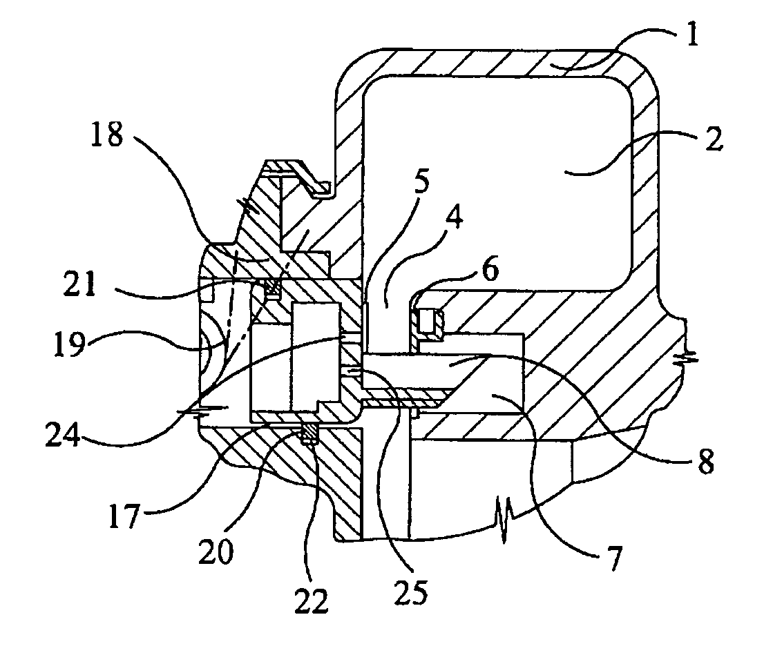
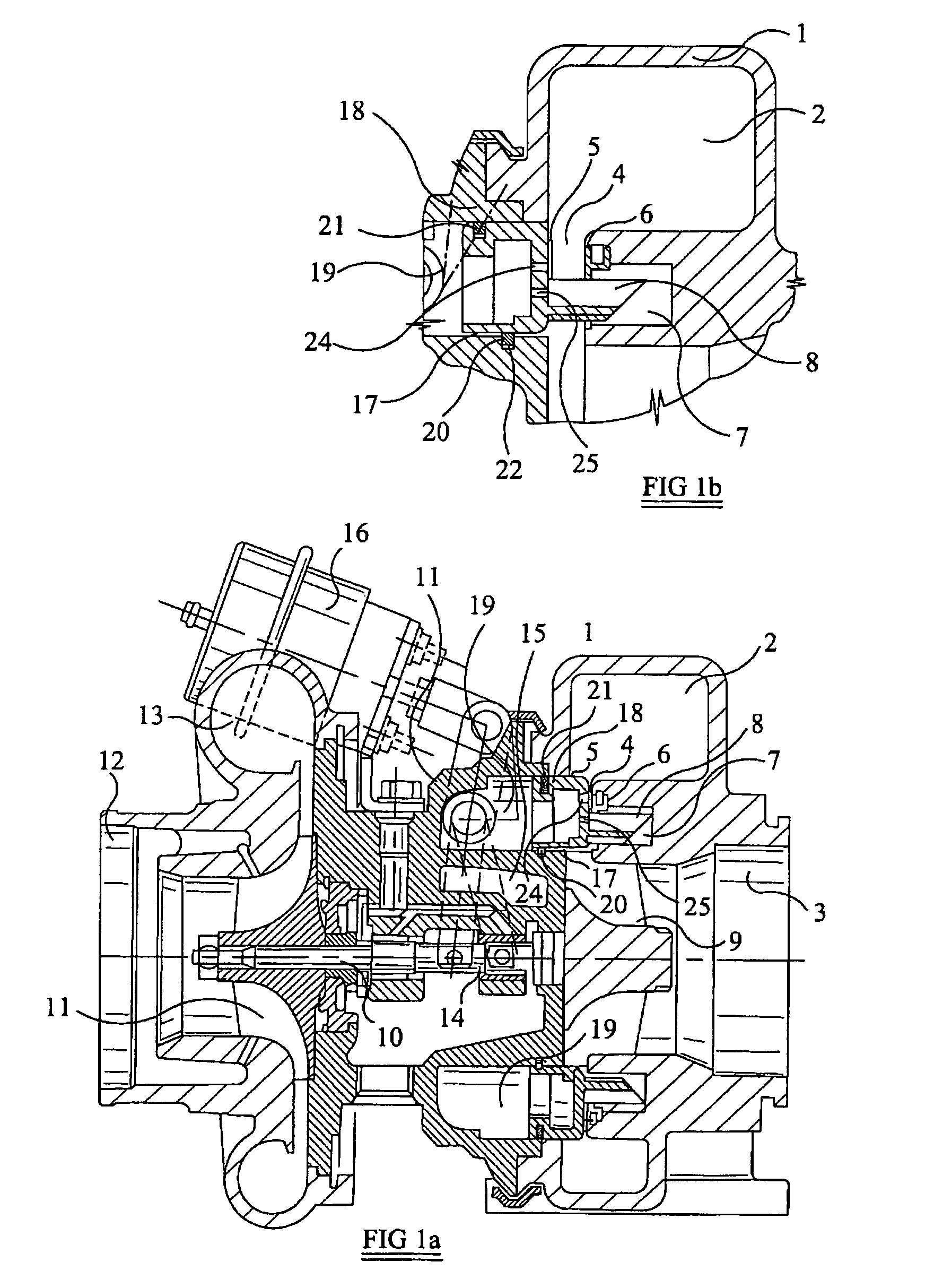
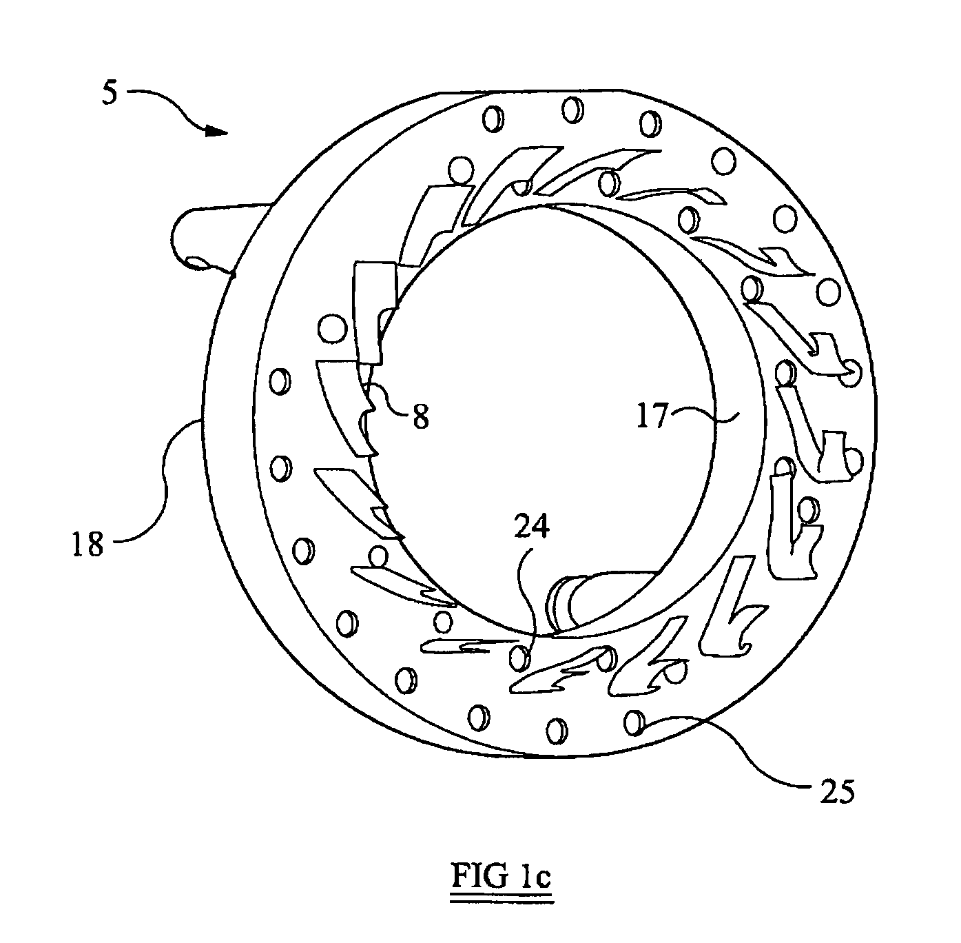
[0024]Referring to FIG. 1a, the illustrated variable geometry turbine comprises a turbine housing 1 defining an inlet chamber 2 to which gas from an internal combustion engine (not shown) is delivered. The exhaust gas flows from the inlet chamber 2 to an outlet passageway 3 via an annular inlet passageway 4. The inlet passageway 4 is defined on one side by the face of a movable annular wall member 5, commonly referred to as a “nozzle ring,” and on the opposite side by an annular shroud 6, which covers the opening of an annular recess 7 in the facing wall.

[0025]Gas flowing from the inlet chamber 2 to the outlet passageway 3 passes over a turbine wheel 9 and as a result torque is applied to a turbocharger shaft 10 that drives a compressor wheel 11. Rotation of the compressor wheel 11 pressurizes ambient air present in an air inlet 12 and delivers the pressurized air to an air outlet 13 from which it is fed to an internal combustion engine (not shown). The speed of the turbine wheel 9 ...


PUM


Abstract

A variable geometry turbine comprises a turbine wheel (9) supported in a housing (1) for rotation about an axis. A nozzle ring (5) is moveably mounted within a cavity (19) provided within the housing for adjustment of the width of an annular inlet passageway (4) extending radially inwards towards the turbine wheel (9). An array of inlet guide vanes (8) extends between a radial face of the nozzle ring (5) and an opposing wall of the inlet (4) defining a radial vane passage. A first circumferential array of apertures (25) is provided through the radial face, each of which lies substantially within the vane passage. A second circumferential array of apertures (24) is also provided in said radial face, each of lies substantially upstream or downstream of the first array (25) of apertures. The inlet (4) and cavity (19) are in fluid communication via both the first and second sets of apertures (25,24).

Description

[0001]The present application is a continuation of PCT / GB2006 / 002069 filed on Jun. 6, 2006. which claims the benefit of United Kingdom Patent Application No. GB0514465.4 filed Jul. 14, 2005 and United Kingdom Patent Application No. GB0511613.2 filed Jun. 7, 2005. Each of the above-referenced applications are incorporated herein by reference.[0002]The present invention relates to a variable geometry turbine, particularly, but not exclusively, for use in a turbocharger of an internal combustion engine.BACKGROUND OF THE INVENTION[0003]Turbochargers are well known devices for supplying air to the intake of an internal combustion engine at pressures above atmospheric pressure (boost pressures). A conventional turbocharger essentially comprises an exhaust gas driven turbine wheel mounted on a rotatable shaft within a turbine housing. Rotation of the turbine wheel rotates a compressor wheel that is mounted on the other end of the shaft and within a compressor housing. The compressor wheel ...

Claims


Application Information

Patent Timeline
Patent Type & Authority Patents(United States)
IPC IPC(8): F01D17/14
CPCF01D17/143F01D17/167F05D2220/40F01D17/14F02C6/12
Inventor PARKER, JOHN FREDERICKLUCK, DAVIDBROWN, DAVID H.
Owner CUMMINS LTD
Why Eureka
Try Eureka