

Self-oscillating transformerless electronic ballast
a transformerless, transformerless technology, applied in the direction of electric variable regulation, process and machine control, instruments, etc., can solve the problems of high monetary cost, poor energy efficiency and flicker, and many operational problems of traditional magnetic coil ballasts, and achieve the effect of simplifying the structur
- Summary
- Abstract
- Description
- Claims
- Application Information
AI Technical Summary
Benefits of technology
Problems solved by technology
Method used
Image

Examples
first embodiment
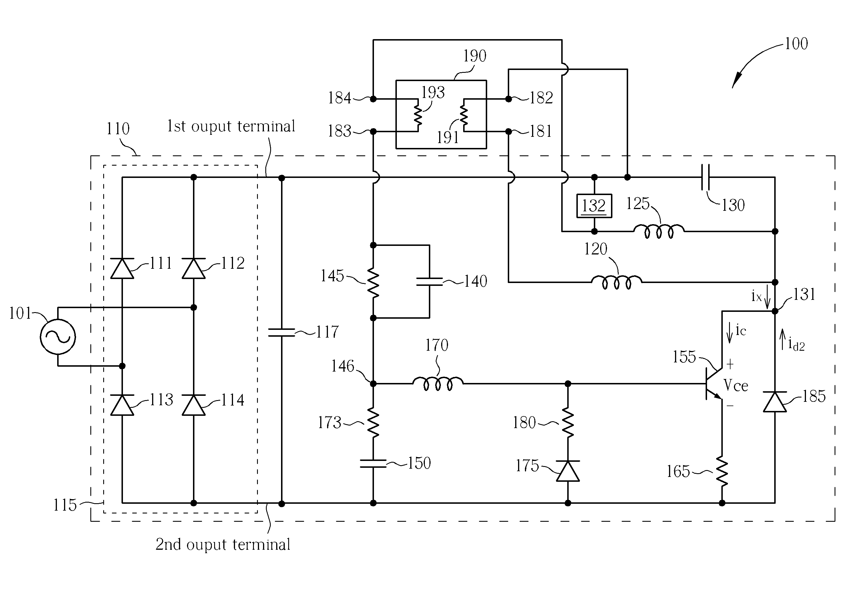
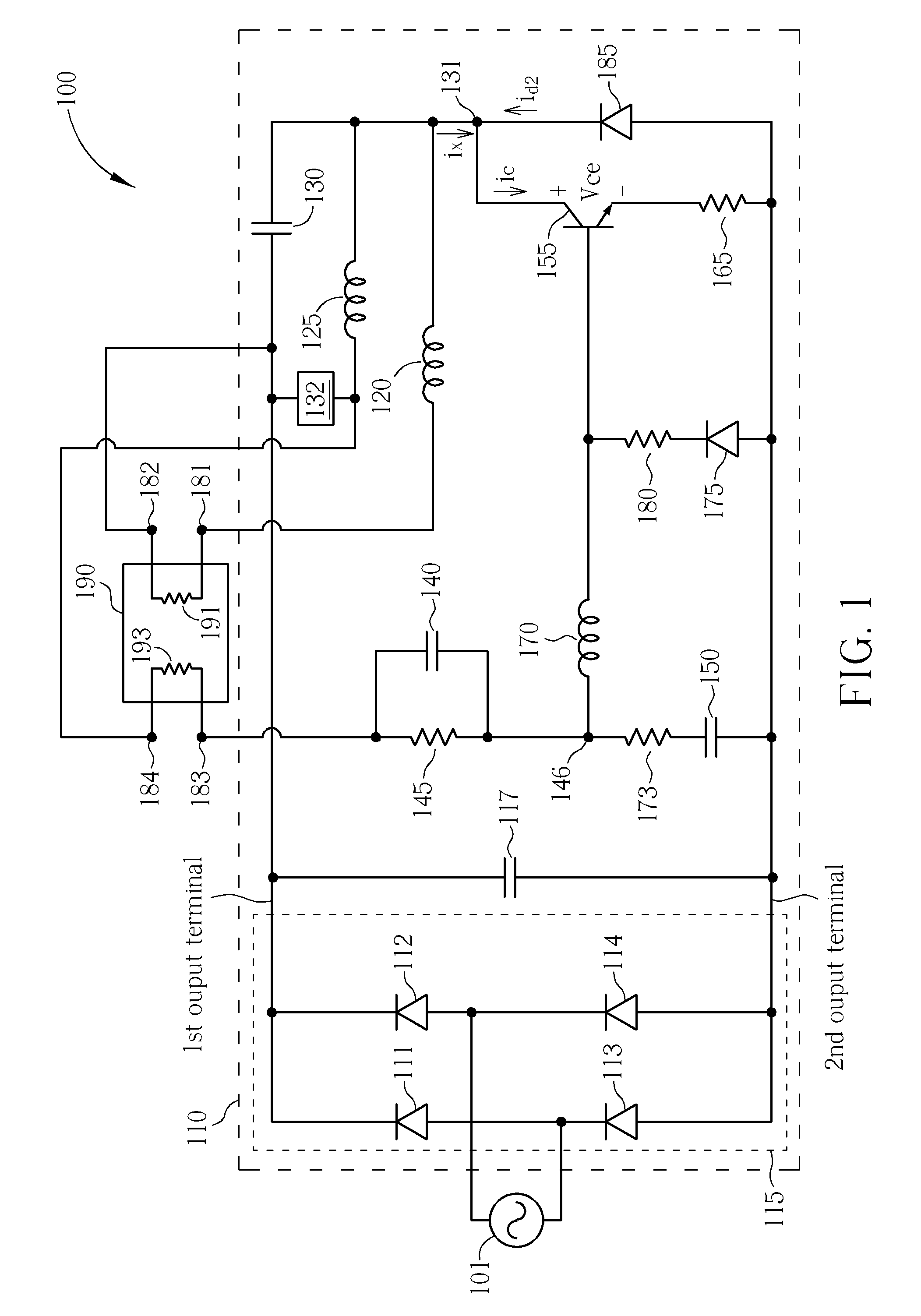
[0020]Please refer to FIG. 1, which is a circuit diagram schematically showing an electronic ballast in accordance with the present invention. As shown in FIG. 1, the lighting system 100 comprises an ac input source 101, a lamp 190 and an electronic ballast 110. The ac input source 101 is employed to generate an ac input voltage. The lamp 190 can be a discharge lamp including a first filament 191 and a second filament 193. In one embodiment, the lamp 190 is a hot-cathode fluorescent lamp (HCFL). In another embodiment, the lamp 190 is a cold-cathode fluorescent lamp (CCFL) or an external electrode fluorescent lamp (EEFL). The first filament 191 is coupled with a first node 181 and a second node 182. The second filament 193 is coupled with a third node 183 and a fourth node 184. The electronic ballast 110 is coupled with the ac input source 101 and the lamp 190 for powering the lamp 190.
[0021]The electronic ballast 110 comprises a rectifier circuit 115, an input capacitor 117, a first...
second embodiment
[0036]Please refer to FIG. 3, which is a circuit diagram schematically showing an electronic ballast in accordance with the present invention. As shown in FIG. 3, the lighting system 300 comprises the ac input source 101, the lamp 190 and an electronic ballast 310. The electronic ballast 310 is similar to the electronic ballast 110 shown in FIG. 1, differing in that the first diode 175, the second diode 185 and the fourth resistor 180 are omitted, and the power switch 155 is replaced with a power switch 355. Also a fourth capacitor 160 is coupled between the control end of the power switch 355 and the ground end (source end) of the power switch 355. The power switch 355 is a MOSFET having a parasitic diode 385 between the output and ground ends thereof as shown in FIG. 3. The parasitic diode 385 is utilized to bypass a current id3 when the power switch 355 is operating in a reverse conduction mode, i.e. for providing the functionality of the second diode 185 omitted. Since there is ...
third embodiment
[0037]Please refer to FIG. 4, which is a circuit diagram schematically showing an electronic ballast in accordance with the present invention. As shown in FIG. 4, the lighting system 400 comprises the ac input source 101, the lamp 190 and an electronic ballast 410. Since the electronic ballast 410 is configured as a class E amplifier to provide a sinusoidal driving signal with very high ac voltage to light the lamp 190, depending on actual design, its ac voltage swing is easily four times the dc voltage while a half-bridge inverter is limited to a rail-to-rail swing of the dc voltage. Therefore, the second capacitor 140 and the first resistor 145 can be coupled with the sixth node 146 and the fourth node 184 as aforementioned in another couple possibility of the lighting system 100, i.e. there is no heating or shutdown mechanism available for the second filament 193. So can the first inductor 120 move to the second node 182 to eliminate heating on the first filament 191. Under such ...
PUM
 Abstract
Description
Claims
Application Information