Broadband micropatch antenna system with reduced sensitivity to multipath reception

a micro-patch antenna and wideband technology, applied in the field of antennas, can solve the problems of inefficient reduction of multi-path reflection sensitivity, small and lightweight, prior-art micro-patch antenna design, etc., and achieve the effects of low sensitivity to multi-path radiation, high bandwidth, and low cos

Active Publication Date: 2012-05-08
TOPCON GPS
View PDF9 Cites 17 Cited by
  • Summary
  • Abstract
  • Description
  • Claims
  • Application Information

AI Technical Summary

Problems solved by technology

Relative to other antenna designs, they are small and lightweight, and they may be manufactured in high volumes at low cost.
This prior-art micropatch antenna design, however, suffers a major disadvantage: reduction in sensitivity to multipath reflection is inefficient in the case of a broadband radiator with lengths of the ground plane on the order of 1-1.5 wavelengths.

Method used


Image

  • Broadband micropatch antenna system with reduced sensitivity to multipath reception
  • Broadband micropatch antenna system with reduced sensitivity to multipath reception
  • Broadband micropatch antenna system with reduced sensitivity to multipath reception

Examples


Embodiment Construction

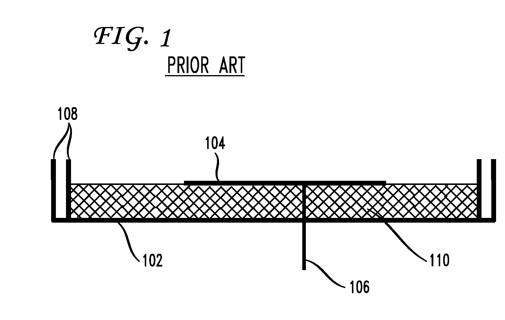
[0024]FIG. 2 shows a basic cross-sectional view of a conventional micropatch antenna. The flat radiating element (patch) 202 is separated from the flat ground plane 204 by a dielectric medium 212. Dielectric medium 212, for example, may be an air gap or a solid dielectric substrate. If the dielectric medium 212 is an air gap, the radiating element 202 and the ground plane 204 may be held together by standoffs, such as ceramic posts (not shown). The length of ground plane 204 is L. The height of radiating element 202 above ground plane 204 is H. If the dielectric medium 212 is air, the height H is equivalent to the air-gap spacing between radiating element 202 and ground plane 204. If the dielectric medium 212 is a solid dielectric substrate, the height H is equivalent to the thickness of the solid dielectric substrate.

[0025]Signals are transmitted to and from the micropatch antenna via a radiofrequency (RF) transmission line. In the example shown in FIG. 2, signals are fed to the ra...


PUM


Abstract

A micropatch antenna system with simultaneous high bandwidth and low sensitivity to multipath radiation is achieved by positioning a radiating element within a cavity in a ground plane. Bandwidth and sensitivity to multipath radiation may be varied by varying the height of the radiating element above the bottom of the cavity and above the top of the ground plane. The electromagnetic and physical characteristics of the antenna system may be further controlled by introducing dielectric solids or wave-slowing structures between the bottom of the cavity and the radiating element. A dual-band micropatch antenna system with simultaneous high bandwidth and low sensitivity to multipath radiation may be similarly configured by stacking a second radiating element on top of the first radiating element.

Description

[0001]This application claims the benefit of U.S. Provisional Application No. 61 / 125,935 filed Apr. 30, 2008, which is incorporated herein by reference.BACKGROUND OF THE INVENTION[0002]The present invention relates generally to antennas, and more particularly to broadband micropatch antenna systems with reduced sensitivity to multipath reception.[0003]Micropatch antennas (MPAs) are widely deployed in global navigation satellite system (GNSS) receivers. Relative to other antenna designs, they are small and lightweight, and they may be manufactured in high volumes at low cost. The basic elements of a conventional MPA are a flat radiating element (patch) and a flat ground plane separated by a dielectric medium. The resonant size of a MPA is a function of the wavelength of the radiation propagating in the dielectric medium between the radiating element and the ground plane. The resonant size is approximately half of the wavelength. The resonant size may be reduced by increasing the perm...

Claims


Application Information

Patent Timeline
Patent Type & Authority Patents(United States)
IPC IPC(8): H01Q1/38H01Q1/42
CPCH01Q9/0407H01Q9/0414H01Q9/0442
Inventor TATARNIKOV, DMITRYASTAKHOV, ANDREYEMELIANOV, SERGEYSTEPANENKO, ANTON
Owner TOPCON GPS
Why Eureka
Try Eureka