Line-stopping sheath spigot assemblies and line-stopping sheath assemblies using the same

a technology of spigot assembly and sheath, which is applied in the direction of branching pipes, manufacturing tools, transportation and packaging, etc., can solve the problems of pipe normally used to fabricate the spigot assembly, pipe may not be fully functioning, and pipeline sections may not be controlled, so as to reduce the cost of fabricating and reduce the thickness of sidewalls

Inactive Publication Date: 2012-05-15
JCM IND
View PDF5 Cites 10 Cited by
  • Summary
  • Abstract
  • Description
  • Claims
  • Application Information

AI Technical Summary

Benefits of technology

[0008]Embodiments of the present principles realize significant advantages over the prior art. For example, in a line-stopping spigot assembly including a flange and a spigot pipe, the spigot is advantageously fabricated with a sidewall that is substantially thinner than the sidewalls of the line-stopping spigot pipes of the prior art. This reduction in sidewall thickness directly reduces the cost of fabricating the spigot assembly, and in turn the cost of fabricating entire line-stopping sleeves.

Problems solved by technology

For example, a section of pipeline may not be controlled by an upstream valve that will allow fluid flow to be shut-off during pipeline repairs.
Alternatively, the pipeline may include a valve, but that valve may be broken or otherwise not fully functioning.
The pipe normally used to fabricate the each spigot assembly is relatively expensive, especially if stainless steel pipe is used.
For example, ⅜ to ½ inch thick stainless steel pipe typically costs on the order of $200 dollars per linear foot, which significantly adds to the cost of each spigot assembly and consequently to the cost of the overall line-stopping sheath assembly.
Moreover, the flange portion of the spigot assembly may be fabricated from stainless steel, which adds further expense and weight to the sheath assembly.

Method used


Image

  • Line-stopping sheath spigot assemblies and line-stopping sheath assemblies using the same
  • Line-stopping sheath spigot assemblies and line-stopping sheath assemblies using the same
  • Line-stopping sheath spigot assemblies and line-stopping sheath assemblies using the same

Examples


Embodiment Construction

[0022]The principles of the present invention and their advantages are best understood by referring to the illustrated embodiment depicted in FIGS. 1-6 of the drawings, in which like numbers designate like parts.

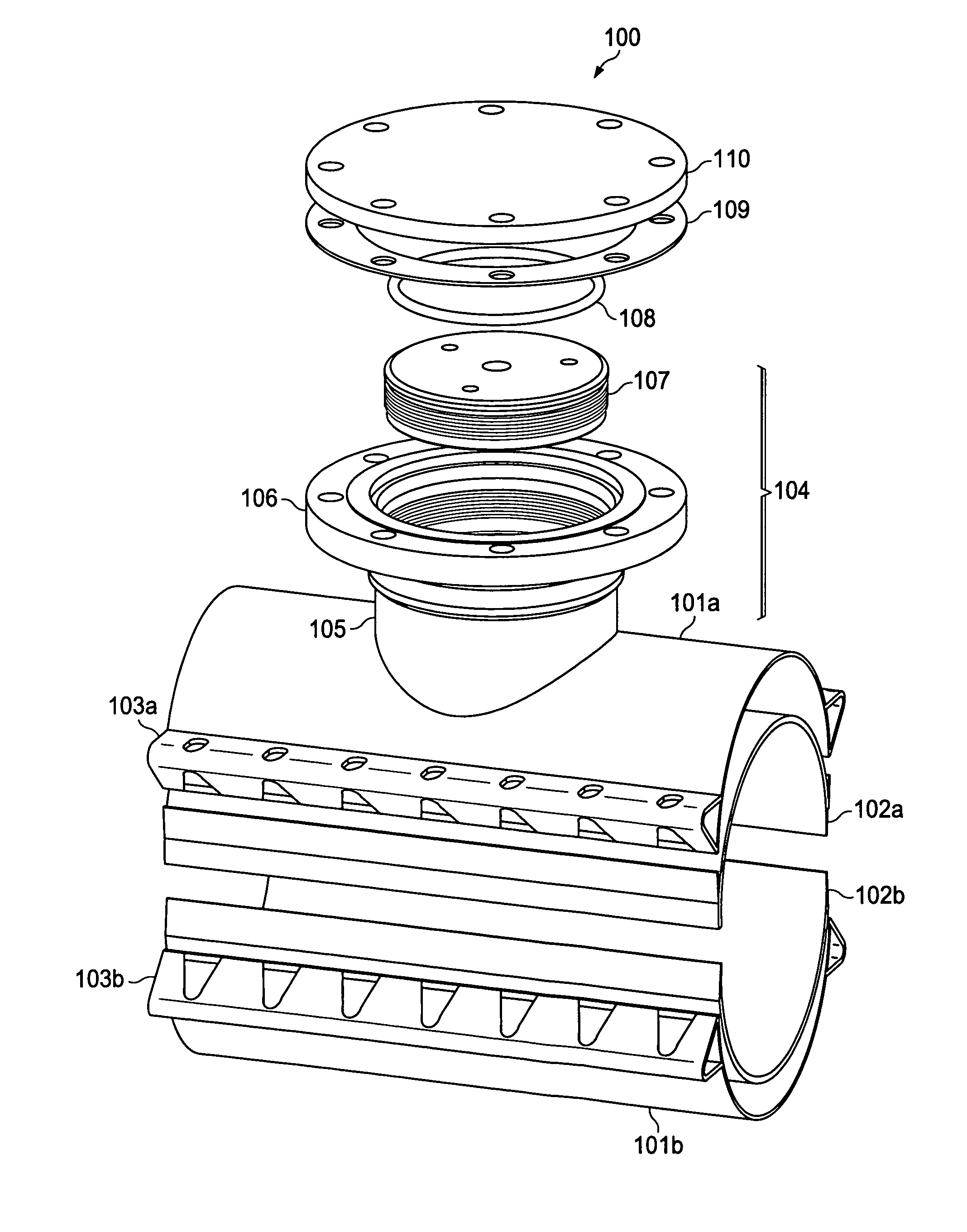
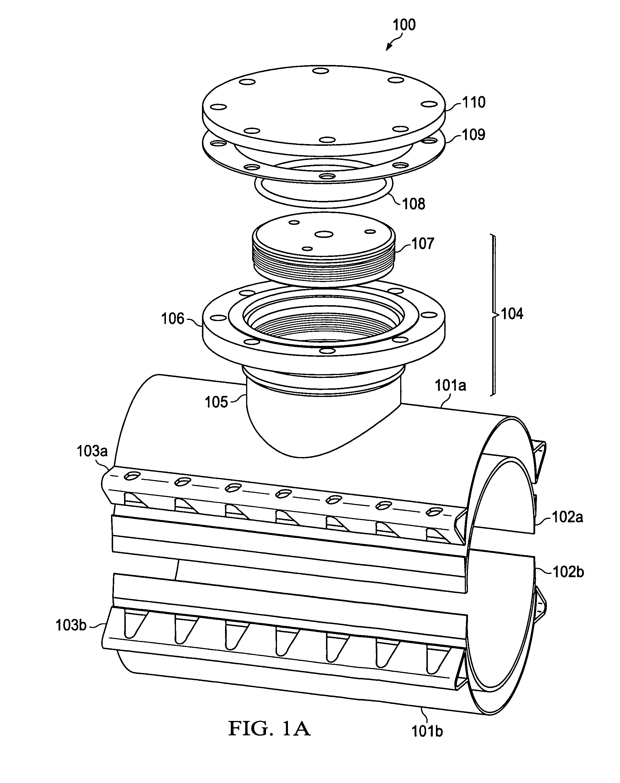
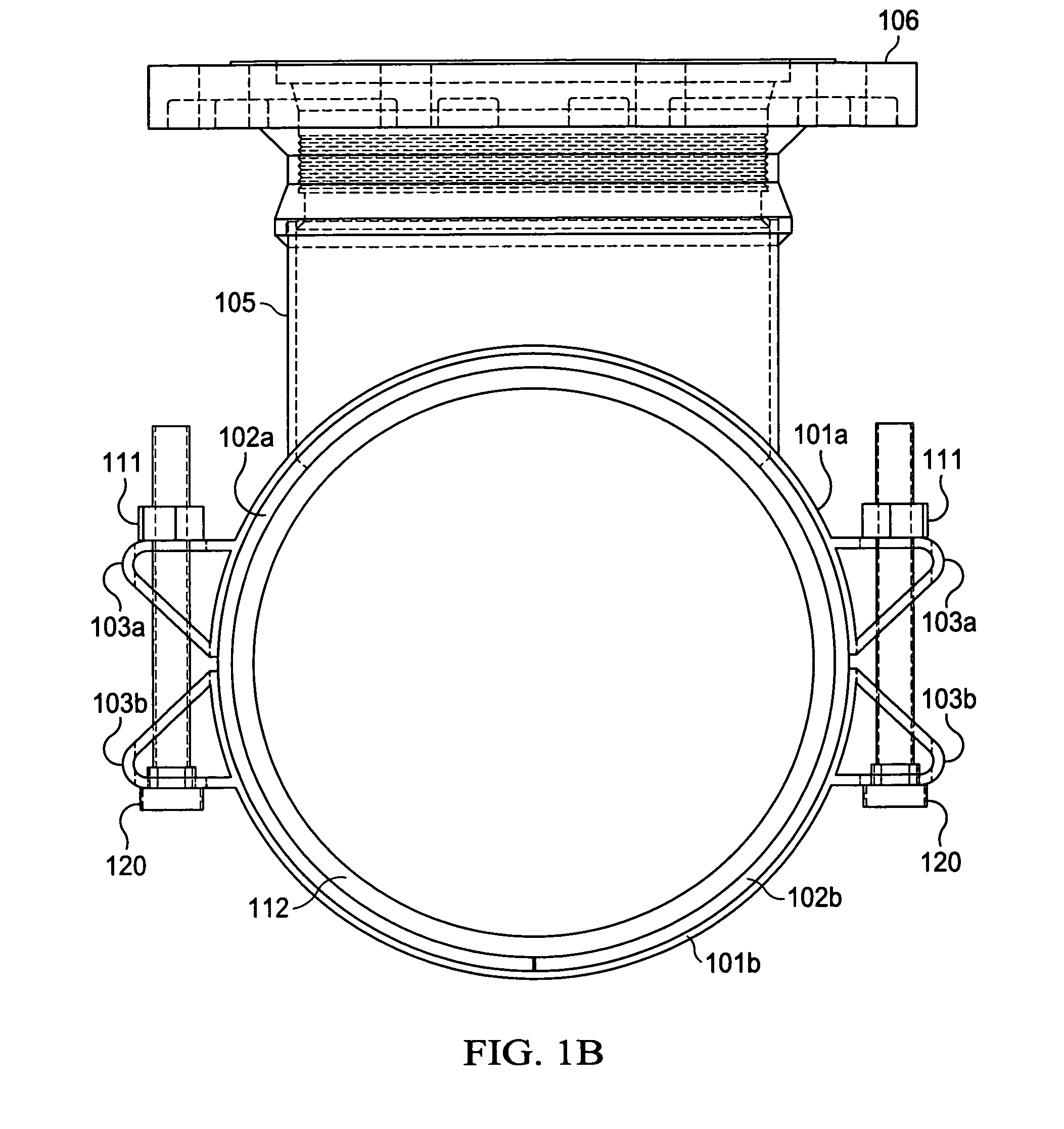
[0023]FIG. 1A is a diagram of an exemplary tapping / plugging sheath assembly 100 embodying the principles of the present invention. As shown in FIG. 1A, tapping / plugging sheath assembly includes first and second half sheaths 101a and 101b, each of which supports a corresponding gasket 102a-102b. Half sheaths 101a-101b are, for example, fabricated from stainless steel, steel, or other rigid material. Gaskets 102a-102b are fabricated, for example, from rubber or other resilient material.

[0024]Half sheaths 101a-101b and gaskets 102a-102b are dimensioned to be disposed around the circular outer surface of a section of pipe being tapped and plugged using the procedure discussed above. Half sheath 101a includes a pair of opposing lugs 103a and half sheath 101b includes a pair of co...


PUM


Abstract

A spigot for a line-stopping sheath assembly includes a flange including a flange plate and a flange barrel. The flange barrel includes a wall extending from the flange plate, with an end of the wall of the flange barrel opposing the flange plate having a projection defining a periphery of a socket area for receiving an end of a pipe. The spigot also includes a pipe having an end disposed within the periphery of the socket area defined by the projection of the flange barrel.

Description

FIELD OF INVENTION[0001]The present invention relates in general to pipeline equipment, and in particular, to line-stopping sheath spigot assemblies and line-stopping sheath assemblies using the same.BACKGROUND OF INVENTION[0002]It is sometimes necessary to stop fluid flow through a pipeline, for example a water pipeline, without the assistance of a valve. For example, a section of pipeline may not be controlled by an upstream valve that will allow fluid flow to be shut-off during pipeline repairs. Alternatively, the pipeline may include a valve, but that valve may be broken or otherwise not fully functioning. In either case, plugging may be used to temporarily shut-off the fluid flow such that needed repairs or other servicing operations can be made to a section pipeline.[0003]In one type of plugging operation, two halves line-stopping sheath or sleeve are placed around the pipe at a point along the pipeline where fluid flow is to be shut-off. The two halves of the sheath are typic...

Claims


Application Information

Patent Timeline
Patent Type & Authority Patents(United States)
IPC IPC(8): F16L23/00
CPCF16L41/12F16L55/11F16L55/1108Y10T137/0458Y10T137/612
Inventor COLLINS, AARON CALDWELL NAJERA
Owner JCM IND
Why Eureka
Try Eureka