Tubular reactor with jet impingement heat transfer

a tubular reactor and heat transfer technology, applied in the field of tubular reactors, can solve the problems of increasing the diameter of the tube and correspondingly increasing the gap between the tube wall and the structured packing

Inactive Publication Date: 2012-05-15
AIR PROD & CHEM INC
View PDF24 Cites 23 Cited by
  • Summary
  • Abstract
  • Description
  • Claims
  • Application Information

AI Technical Summary

Benefits of technology

[0081]A particular benefit of the present method is that heat transfer is not degraded due to the tube wall creeping after extended operation. Heat transfer is degraded in previous methods that rely on squeezing of the fluid between the insert and the tube wall because when the tube wall diameter increases, the gap between the insert and the tube wall increases resulting in a lower velocity of the fluid. The lower velocity results in decreased heat transfer.

Problems solved by technology

A problem with this approach and any approach where heat transfer relies on the gap between the structure and the tube wall, is that after extended operation at high temperature and pressure, the tube may experience time-dependent plastic deformation, commonly known as “creep,” resulting in an increase in the tube diameter and a corresponding increase in the gap between the tube wall and the structured packing.

Method used


Image

  • Tubular reactor with jet impingement heat transfer
  • Tubular reactor with jet impingement heat transfer
  • Tubular reactor with jet impingement heat transfer

Examples


example

[0146]The technical effect of the plurality of orifices for jet impingement heat transfer was investigated using Computational Fluid Dynamics (CFD) modeling.

[0147]CFD modeling was validated against heat transfer experiments.

[0148]Heat transfer experiments were carried out for various packings. The heat transfer coefficient was measured as a function of the pressure drop through the tube. The experiments were conducted using air as the fluid and the tube was electrically heated. The experiments were conducted at roughly atmospheric pressure and ambient temperature. The heat transfer coefficient was calculated from wall temperature measurements for various flow rates.

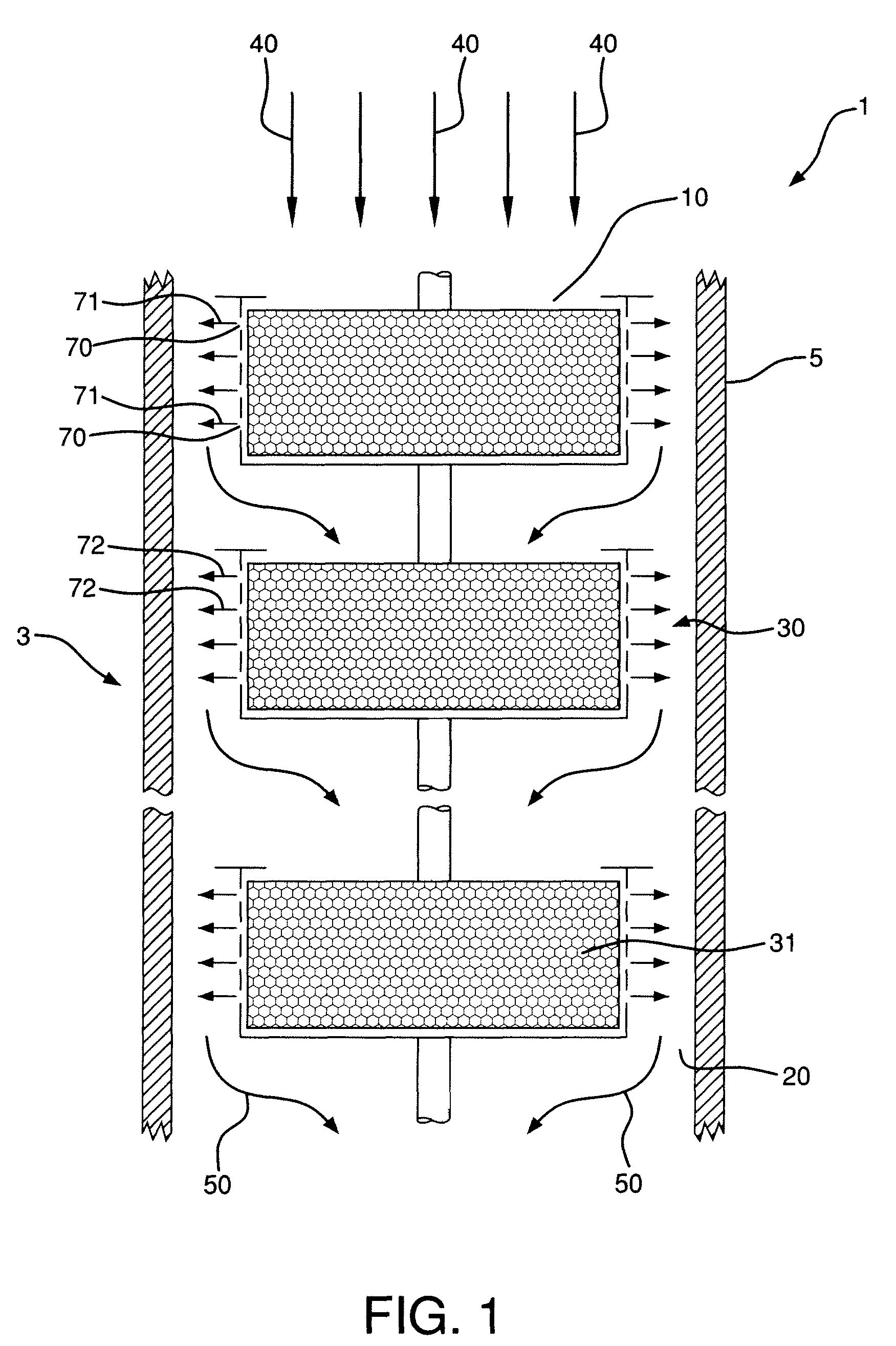
[0149]The results of CFD simulations are compared to experimental data in FIG. 5. for the “cup design,” similar to the structure illustrated in FIG. 2. In the “cup design,” the spacing between the orifice opening and the tube wall is about 3 mm. The metal structure had a length of about 66 mm, with a 18 mm distance betwee...


PUM

PropertyMeasurementUnit
pressureaaaaaaaaaa
temperatureaaaaaaaaaa
angleaaaaaaaaaa

Abstract

A tubular reactor and method for producing a product mixture in a tubular reactor where the tubular reactor comprises an internal catalytic insert having orifices for forming fluid jets for impinging the fluid on the tube wall. Jet impingement is used to improve heat transfer between the fluid in the tube and the tube wall in a non-adiabatic reactor. The tubular reactor and method may be used for endothermic reactions such as steam methane reforming and for exothermic reactions such as methanation.

Description

BACKGROUND[0001]The present invention relates to a method and tubular reactors for producing a product mixture from a reactant mixture. More specifically, the present invention relates to improving heat transfer in tubular reactors.[0002]Reactors containing packings with catalyst have been described, for example, tubular reactors used in steam methane reforming. The packings may be random packings such as catalyst pellets or so-called structured packing. Structured packing, as compared to random packings, can produce lower pressure drop, are not easily fluidized, and are not prone to settling or crushing. Since tubular reactors are often externally heated or cooled, another important characteristic of the reactor is related to heat transfer between the external heat source / sink and the process fluid within the reactor.[0003]Tubular reactors may contain random packing or structured packing where the packing includes catalyst for the desired reaction. Structured packing has been credi...

Claims


Application Information

Patent Timeline
Patent Type & Authority Patents(United States)
IPC IPC(8): B01J8/02
CPCB01J8/0426B01J8/0496B01J10/007B01J19/32C01B3/382C01B3/384B01J2219/30475B01J2219/32206B01J2219/3221B01J2219/32227B01J2219/32237B01J2219/32408B01J2219/32466C01B2203/0233C01B2203/0811C01B2203/1011C01B2203/1035C01B2203/1241C01B2203/1247C01B2203/142C01B2203/143
Inventor HE, XIAOYIBROEKHUIS, ROBERT ROGERGARG, DIWAKARJIN, BOLICHT, WILLIAM ROBERTTENTARELLI, STEPHEN CLYDE
Owner AIR PROD & CHEM INC
Why Eureka
Try Eureka