Proppant having a glass-ceramic material

a technology of glass-ceramic materials and proppants, applied in the field of proppants, can solve the problems of low specific gravity of high-strength proppants, low flexural strength and stiffness, and high cost of conventional high-strength materials, and achieve the effect of increasing the rigidity module and improving the thermal expansion coefficien

Active Publication Date: 2012-05-15
HALLIBURTON ENERGY SERVICES INC
View PDF209 Cites 32 Cited by
  • Summary
  • Abstract
  • Description
  • Claims
  • Application Information

AI Technical Summary

Benefits of technology

[0002]The present invention relates to proppants and methods to make the proppants and uses of the proppants. In the present invention, the proppant or a portion thereof has a glass-ceramic material present. The presence of a glass-ceramic material can provide one or more benefits, such as increased stiffness (or modulus of rigidity, “MOR”), a desirable coefficient of thermal expansion, and / or other benefits.
[0003]Proppants are materials pumped into oil or gas wells at extreme pressure in a carrier solution (typically brine) during the hydrofracturing process. Once the pumping-induced pressure is removed, proppants “prop” open fractures in the rock formation and thus preclude the fracture from closing. As a result, the amount of formation surface area exposed to the well bore is increased, enhancing recovery rates.
[0005]A feature of the present invention is to provide a proppant having an improved coefficient of thermal expansion. Another feature of the present invention is to provide a proppant that can provide increased stiffness (modulus of rigidity).
[0006]An additional feature of the present invention is to provide a proppant having better resistance to fracturing.
[0007]A further feature of the present invention is to provide a proppant that can have less discreet interfaces between various layers that can form the proppant.

Problems solved by technology

These conventional high strength materials are expensive, however, because of a limited supply of raw materials, a high requirement for purity, and the complex nature of the manufacturing process.
In addition, such high strength materials have high specific gravity, in excess of 3.0, which is highly undesirable for proppant applications.
Producing high strength proppants with low specific gravity is also a challenge.
While light weight oxide materials, such as cordierite, have low specific gravity, they have a relatively weak flexural strength and stiffness.

Method used


Image

  • Proppant having a glass-ceramic material
  • Proppant having a glass-ceramic material
  • Proppant having a glass-ceramic material

Examples


example 1

[0154]A proppant according to the present invention can be prepared by coating conventional glass cenospheres with alkali metals. The alkali metals can be dip-coated, spin coated, and spray-coated onto the glass cenospheres. Alternatively, the cenospheres can be doped with transitional metal oxides. Once the cenospheres are coated or doped, as described, they are subjected to heat treatment for crystallization. The cenospheres are heated to temperatures of 500° C. to 1,000° C. for a period of time sufficient to crystallize at least an outer surface of the cenospheres. The amount of time in which the cenospheres are heated can vary depending on the degree of crystallization desired. The cenospheres can be heated, for example, for a period of about 30 minutes to 12 hours, or from 2 hours to 10 hours. If full crystallization of the cenospheres is desired, the cenospheres should be heated for a fraction of an hour to several hours, for example, 0.1 to 10 hours or more.

[0155]Once the des...

example 2

[0156]

TABLE 1Chemical compositions (in wt %) of two cenosphere samples used forglass-ceramic synthesisSiO2Al2O3Fe2O3MgOCaONa2OK2OTiO2P2O5MnO62.0523.405.891.491.521.182.610.980.210.0659.2926.123.021.33.622.131.250.610.060.02

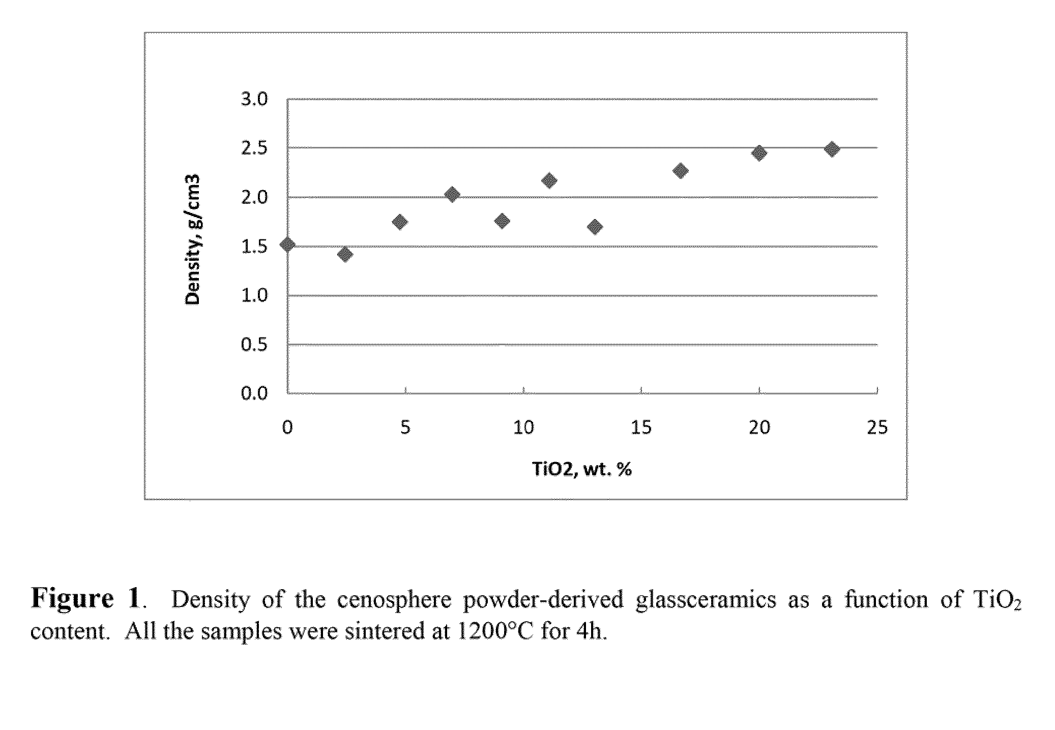
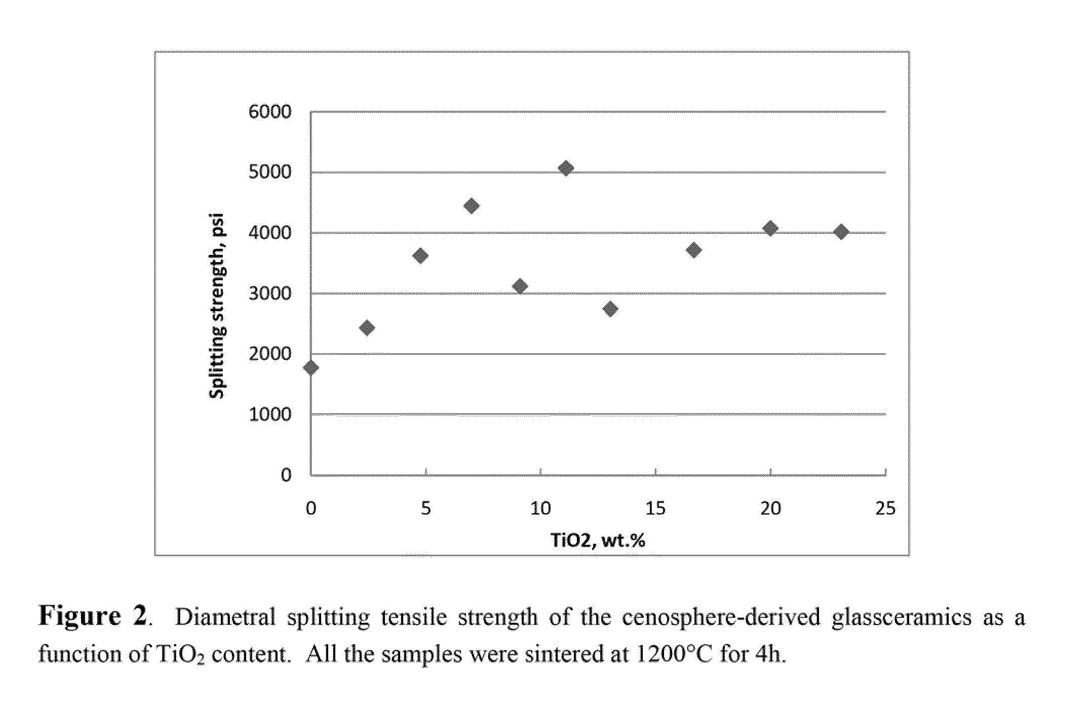
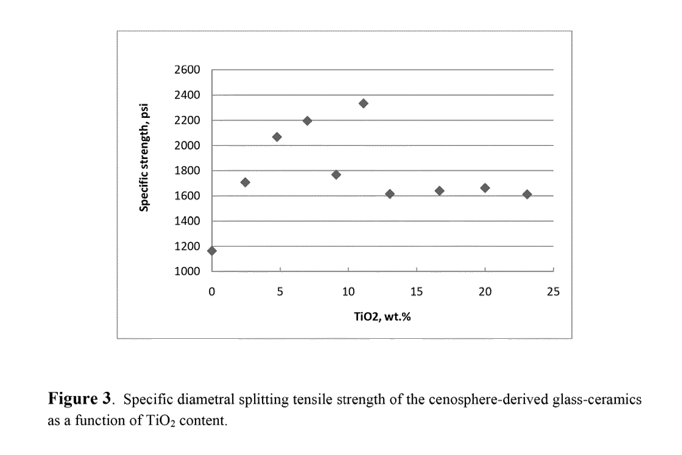
[0157]The two cenosphere samples above were each reduced to powder so as to have an average particle size of approximately 6 μm. Then, circular pellets (spheres) were made with each of the powders, wherein some of the powder mixtures had various levels of TiO2 added as shown in FIG. 1. The circular pellets were then sintered at 1200° C. for 4 h. The results are set forth in FIGS. 1-3 and Table 2. As shown, the addition of TiO2 was very effective in strength improvement. FIG. 1 shows the density as a function of TiO2 content. As can be seen in FIGS. 2 and 3, the strength of the samples increased steeply with a general increase of TiO2 content, but there is a valley at 13 wt % TiO2. The maximum strength was observed at 13 wt % TiO2. The strength was more than double...

example 3

[0159]In this example, additional proppants were prepared using the first cenosphere powder in Table 1 with cordierite. In particular, the mixture (before taking into account the amount of the TiO2 present) was composed of 25 wt % cenosphere powder and 75 wt % cordierite and this mixture was formed into spheres, with the indicated additions of TiO2, and sintered at 1260° C. for 6 h. The density and strength data of the samples are set forth in Table 3. The splitting strength of the composite increased gradually with the content of the TiO2 and reached the maximum at 7 wt % TiO2. The amount of TiO2 is based on the total weight of the pellet or sphere. The strength at this TiO2 level was more than doubled (108% net strength increase over the control) higher than the sample without any TiO2. The strength increase is mainly attributed to the glass-ceramic formation in the cenosphere powder. With the TiO2 content increase, the strength of these 1260° C. sintered composite samples increas...


PUM

PropertyMeasurementUnit
Krumbein sphericityaaaaaaaaaa

Abstract

The present invention relates to glass-ceramic proppants which can be used to prop open subterranean formation fractions, as well as other uses. Proppant formulations are further disclosed which use one or more proppants of the present invention. Methods to prop open subterranean formation fractions are further disclosed. In addition, other uses for the proppants of the present invention are further disclosed, as well as methods of making the glass-ceramic proppants.

Description

[0001]This application claims the benefit under 35 U.S.C. §119(e) of prior U.S. Provisional Patent Application No. 61 / 289,014, filed Dec. 22, 2009, which is incorporated in its entirety by reference herein.[0002]The present invention relates to proppants and methods to make the proppants and uses of the proppants. In the present invention, the proppant or a portion thereof has a glass-ceramic material present. The presence of a glass-ceramic material can provide one or more benefits, such as increased stiffness (or modulus of rigidity, “MOR”), a desirable coefficient of thermal expansion, and / or other benefits.[0003]Proppants are materials pumped into oil or gas wells at extreme pressure in a carrier solution (typically brine) during the hydrofracturing process. Once the pumping-induced pressure is removed, proppants “prop” open fractures in the rock formation and thus preclude the fracture from closing. As a result, the amount of formation surface area exposed to the well bore is i...

Claims


Application Information

Patent Timeline
Patent Type & Authority Patents(United States)
IPC IPC(8): C09K8/62C04B35/00
CPCC03C10/0045C03C11/00C04B35/62695C04B35/62807C09K8/80C09K8/805C04B2235/3232C04B2235/3463C04B2235/528C04B2235/5436Y10S507/904Y10S507/906B32B17/02E21B43/267
Inventor XIE, YUMINGCHATTERJEE, DILIPCOKER, CHRISTOPHER E.FANG, CHRISTOPHER Y.
Owner HALLIBURTON ENERGY SERVICES INC
Why Eureka
Try Eureka