
Combined communications system, prohibiting-signal transmitting apparatus, wireless base station, and method

a communications system and signal transmission technology, applied in the field of combined communications systems, can solve the problems of limiting wireless frequency resources, not being easy to uniformly allocate to all countries and regions, and freedom in allocating a required frequency band

Inactive Publication Date: 2012-05-15
NTT DOCOMO INC
View PDF5 Cites 8 Cited by
  • Summary
  • Abstract
  • Description
  • Claims
  • Application Information

AI Technical Summary

Benefits of technology

This approach allows for effective frequency utilization by preventing interference between old and new communication systems, optimizing bandwidth allocation and reducing the limitations imposed by varying frequency usage across regions and systems.

Problems solved by technology

On the other hand, there is a limit to wireless frequency resources.
Taking into account such circumstances as described above, it will not be easy to uniformly allocate to all countries and regions, exclusively for new systems in the future, a wide, single bandwidth.
Thus, it is anticipated that, depending on applications, the degree of freedom in allocating a required frequency band will be somewhat limited, making frequency allocations more difficult.
As disclosed in Non-patent document 1, in a scheme such that the location of use of the frequency band as well as the transmit power level are restricted in a fixed manner, even when there are no existing terminals in the vicinity that may be interfered with, the location of use and the transmit power level is restricted, which is not desirable from the point of view of effectively utilizing frequencies.
Frequency resources available for a new system could be severely limited especially when the utilization of frequencies vary from one region to another or existing communications systems which are not frequently used use various frequency bands.
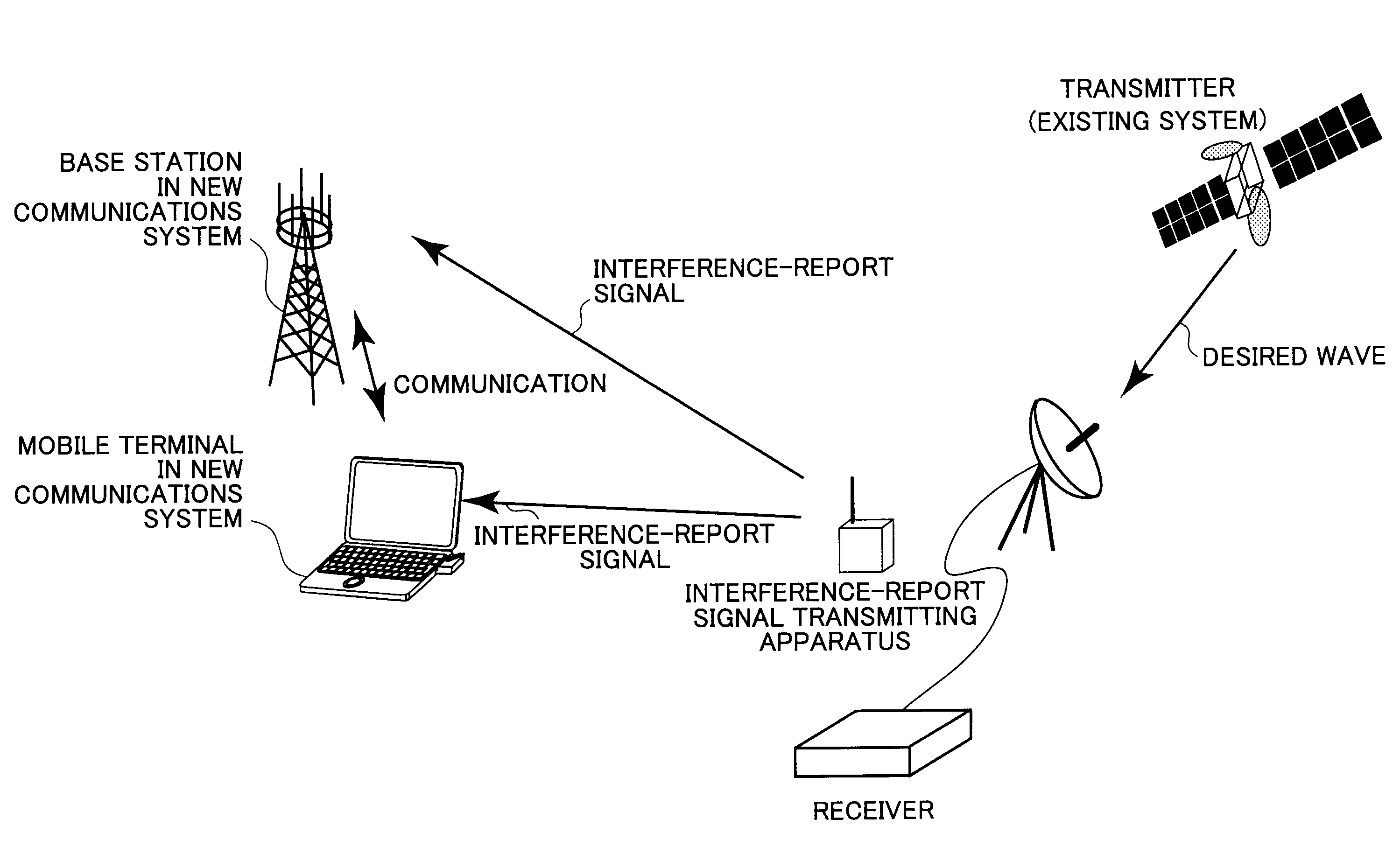
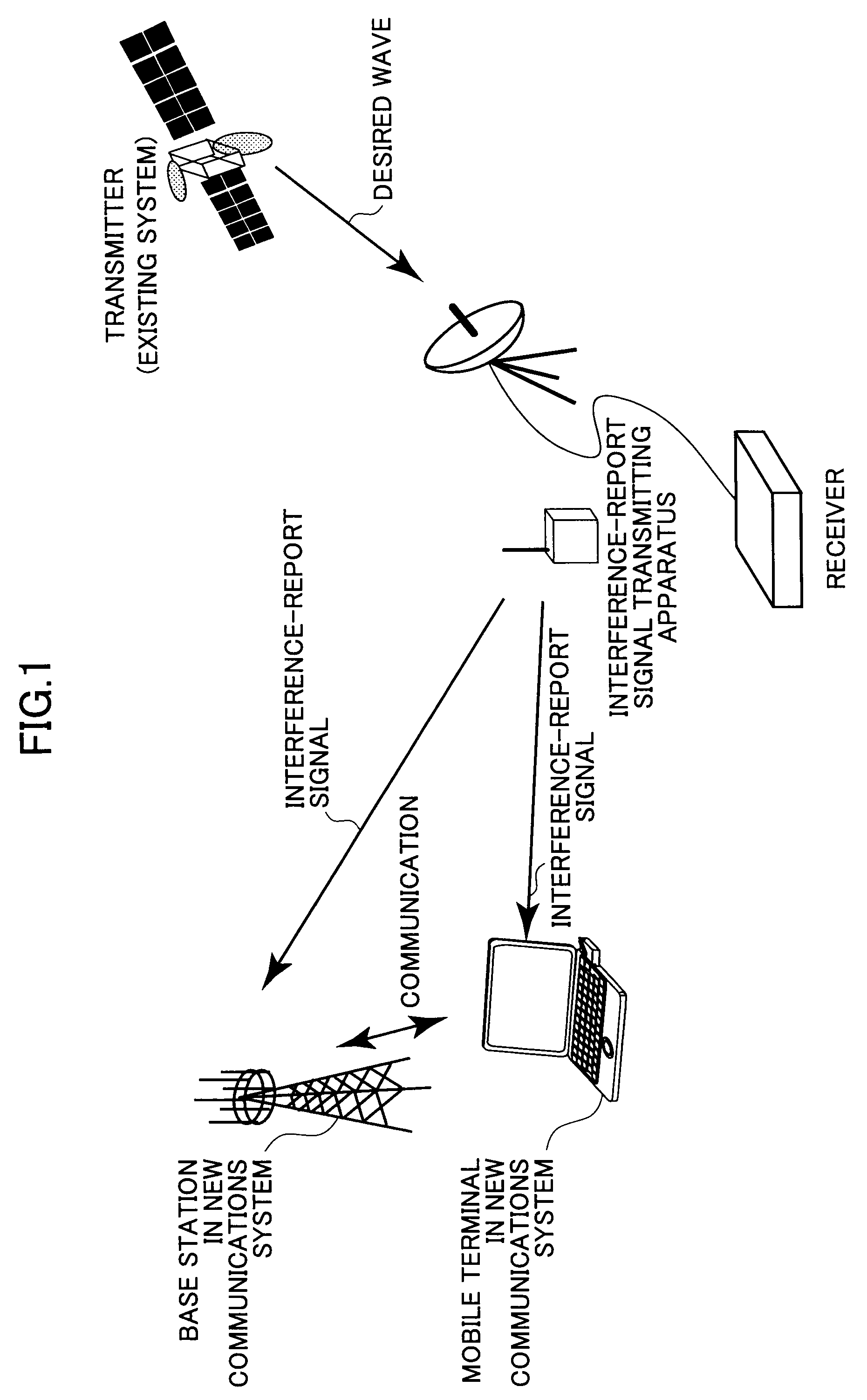
Moreover, as disclosed in Non-patent document 2, with a scheme of detecting whether an existing system is being utilized in the vicinity to avoid interference, when the existing system is a broadcast receiver or a satellite-system receiver, effectively avoiding interference may be difficult.
This means that resources allocatable to a new system may be very limited.
This is because, for example, regardless of whether a receiver of the existing system operates in the vicinity of each transmitter, the new system operation is restricted to the whole of the large broadcasting area.
This aspect is also not desirable regarding effectively utilizing frequencies.
Moreover, for seeking to detect the receiver operation of the existing system, as the receiver itself of the broadcasting system does not transmit any signal, it is simply difficult to appropriately detect the receiver of the broadcasting system with the new system.

Method used


Image

  • Combined communications system, prohibiting-signal transmitting apparatus, wireless base station, and method
  • Combined communications system, prohibiting-signal transmitting apparatus, wireless base station, and method
  • Combined communications system, prohibiting-signal transmitting apparatus, wireless base station, and method

Examples


embodiment 1

[0049]FIG. 4 is an exemplary configuration of a base station of a new system. A signal received by a wireless circuit as shown on the right is separated into a signal with an interference report signal possibly included, and a new system signal. Then, the signal with the interference report signal possibly included is input into an interference-report signal detector.

[0050]If the received signal has an interference report signal included, the interference-report signal detector determines a usage-restricted band from the interference-report signal, and reports the determined result to a resource allocator. As described above, the usage-restricted band is in use by the existing system in actual communications.

[0051]The resource allocator allocates uplink and downlink channel resources using a band other than a usage-restricted band. In the band actually used by the existing system, the base station of the new system must ensure that all signals including not only a normal data signal...

embodiment 2

CSMA

[0117]In FIG. 7, (a) shows an increased likelihood of collision of interference-report signals with an increased geographical density of the interference-report signal transmitting apparatuses. In the illustrated example, signals B and C collide with each other. With respect to this problem, CSMA / CA, and separating into slots, which are conventionally proposed interference avoidance schemes may be used.

[0118]When a CSMA-based method is used, the vicinity is monitored before transmitting a signal such as traffic data, and whether the interference report signal is transmitted in the vicinity is checked. If the interference report signal is transmitted in the vicinity, transmitting of the interference report signal from the own station is postponed until the next opportunity for transmitting ((b) in FIG. 7). On the other hand, if the interference report signal is not transmitted in the vicinity, the interference report signal from the own station is transmitted.

[0119]Separating Int...

embodiment 3

[0134]As the interference-report signals restrict the use of wireless resources by the new system base station, it is not desirable from the point of view of efficiently utilizing frequencies for the interference-report signals to be transmitted more than necessary. Moreover, even in the existing system, it is not desirable from the point of view that the power in the existing system interference-report signal transmitting apparatus is wasted, or the likelihood of collision among the interference-report signals increases.

[0135]In the third embodiment of the present invention, the interference-report signal transmitting apparatus transmits an interference-report signal only when a corresponding existing system receiver is in operation, and does not transmit an interference-report signal when it is not in operation. Therefore, the interference-report signal transmitting apparatus requires a function of determining whether the existing system receiver is in operation. This function may...


PUM


Abstract

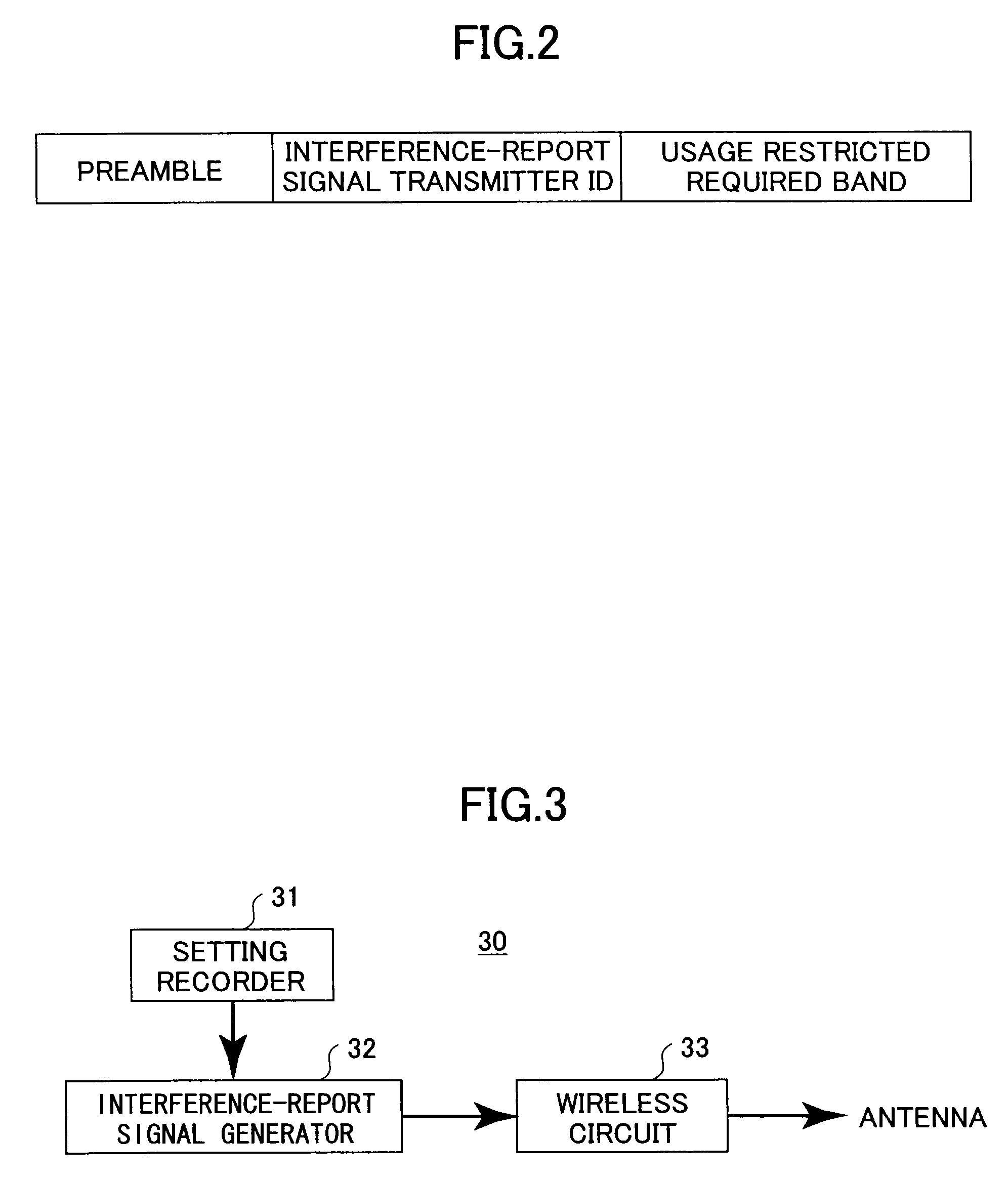
A prohibiting-signal transmitting apparatus for use in a combined system such that there is at least a partial overlap between bands allocated to an old communications system and bands allocated to a new communications system is disclosed. The apparatus includes a unit which monitors for a band-in-use, over which communications are actually being conducted, out of the bands allocated to the old communications system; a unit which generates a prohibiting signal indicating that the band-in-use should not be used in the new communications system; and a unit which transmits the prohibiting signal to a communications apparatus of the new communications system.

Description

BACKGROUND OF THE INVENTION[0001]1. Field of the Invention[0002]The present invention is related to a combined communications system having multiple communications systems including a new communications system and an old communications system, of which system bandwidths overlap at least partially.[0003]2. Description of the Related Art[0004]Wireless communications are utilized in various applications such as mobile telephone, wireless LAN, broadcasting (terrestrial, satellite), radar, and positioning. It is anticipated that frequency allocations will be considered with respect to these existing systems and also in the future with respect to new systems such as the third generation (3G) mobile communications system-evolved long-term evolution (LTE) system, which is being considered in 3GPP, and the fourth generation mobile communications systems. In addition, with a trend toward higher-speed mobile communications systems in recent years, there is also a trend toward an increased band...

Claims


Application Information

Patent Timeline
Patent Type & Authority Patents(United States)
IPC IPC(8): H04M1/00
CPCH04W16/14H04W48/02H04W88/06
Inventor FUJII, HIROMASAYOSHINO, HITOSHI
Owner NTT DOCOMO INC
Learn More