
Method for gas filling of a handle portion of a container

a technology for gas filling and container, which is applied in the field of gas filling a handle portion of a container, can solve the problems of adverse effect of the filling capacity of the filling machine, and achieve the effect of high speed

Active Publication Date: 2012-05-22
ECOLEAN
View PDF8 Cites 39 Cited by
  • Summary
  • Abstract
  • Description
  • Claims
  • Application Information

AI Technical Summary

Benefits of technology

[0008]A further object is to provide a method of this kind which allows high-capacity production of finished containers.
[0009]It is also an object of the present invention to provide a container having a handle portion that can be filled with gas and sealed at high speed.
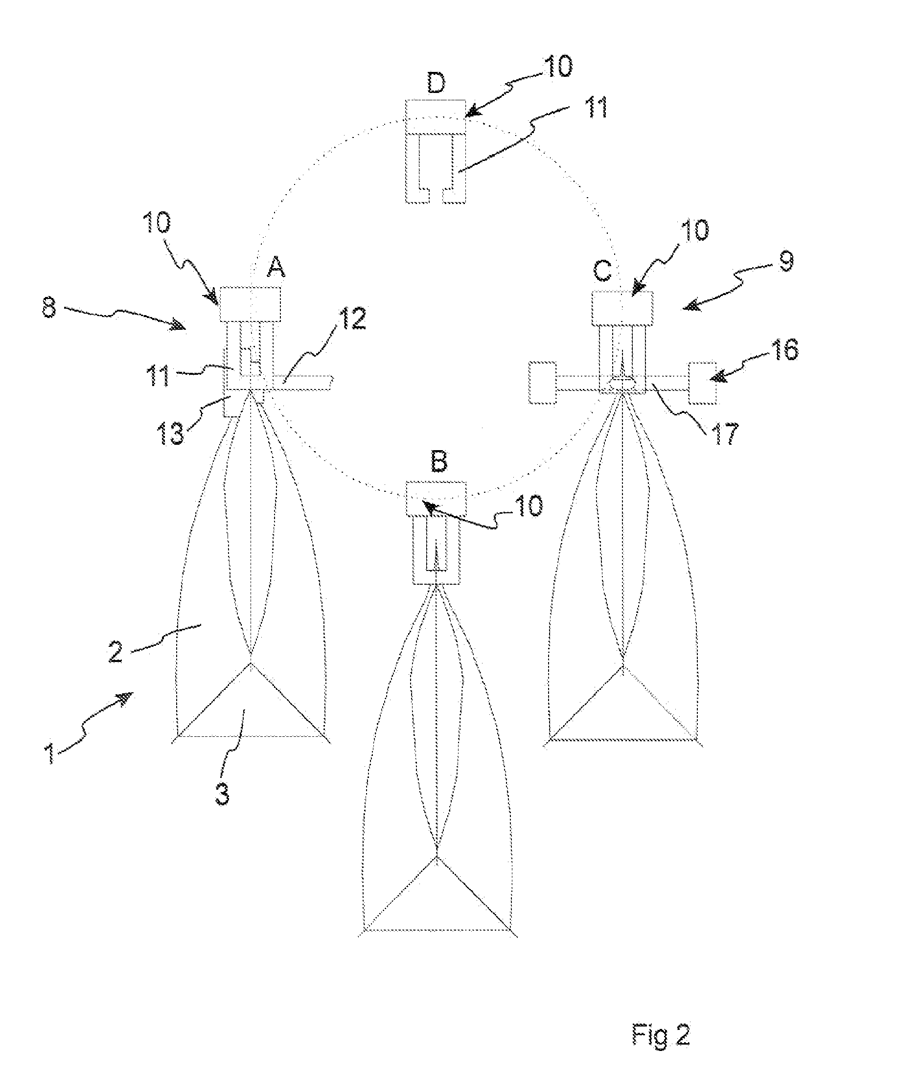
[0012]An improved method for gas filling a handle portion of a container of a collapsible type is thus obtained, since the method allows high-capacity production of finished containers. The handle portion is filled with gas at a first station, whereupon the duct is blocked by a squeezing action. The container is then transported to a second station while maintaining the squeezing action. At this second station, the duct is sealed while maintaining the squeezing action. By dividing the gas filling and sealing operations into two steps, which are carried out at two separate stations, it is possible to shorten the dwell time at each station, whereby the container production capacity can be increased.

Problems solved by technology

It has been found that the filling of gas into the handle portion of containers of a collapsible type may be a bottleneck with an adverse effect on the filling capacity of a filling machine.

Method used


Image

  • Method for gas filling of a handle portion of a container
  • Method for gas filling of a handle portion of a container
  • Method for gas filling of a handle portion of a container

Examples


Embodiment Construction

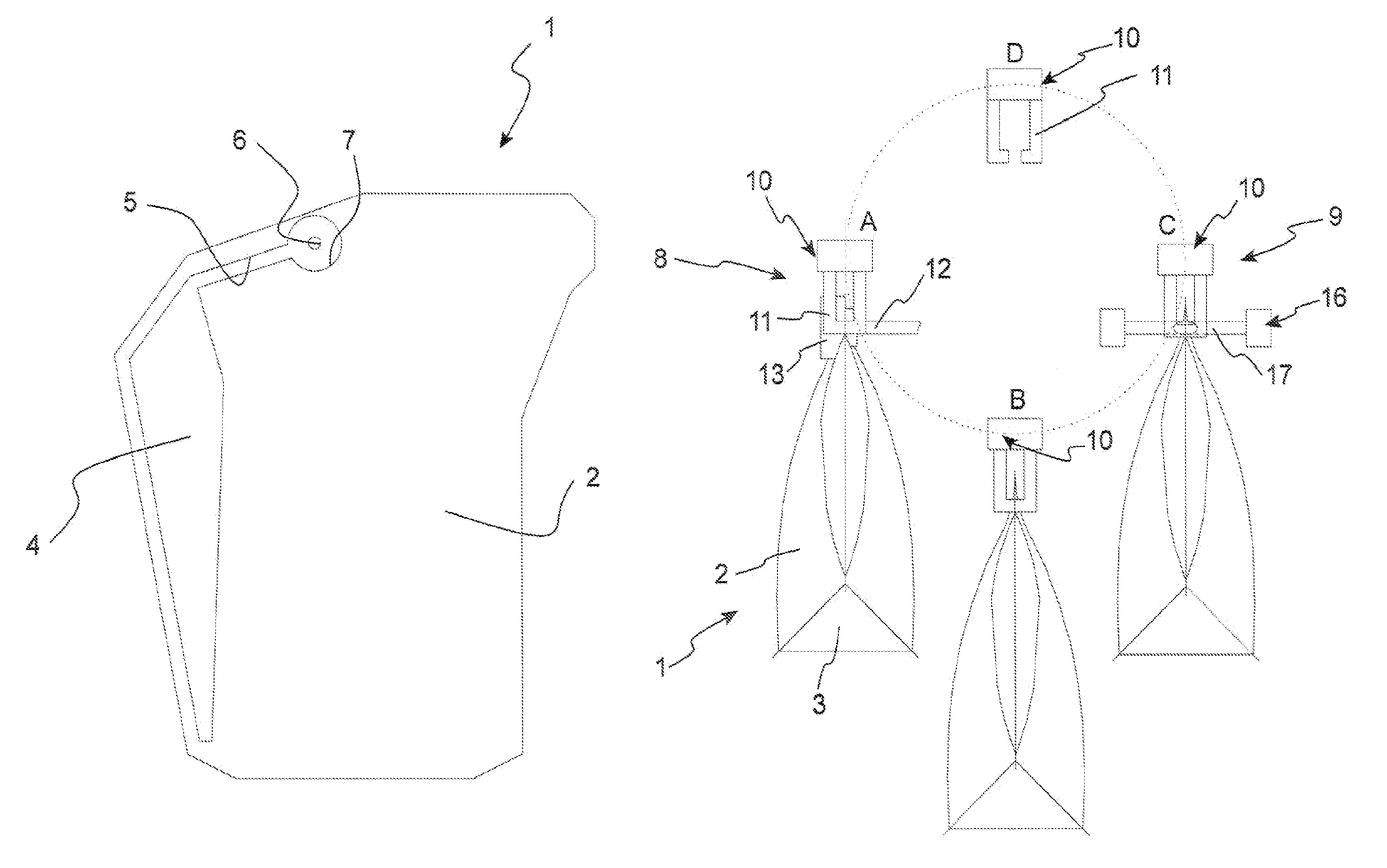
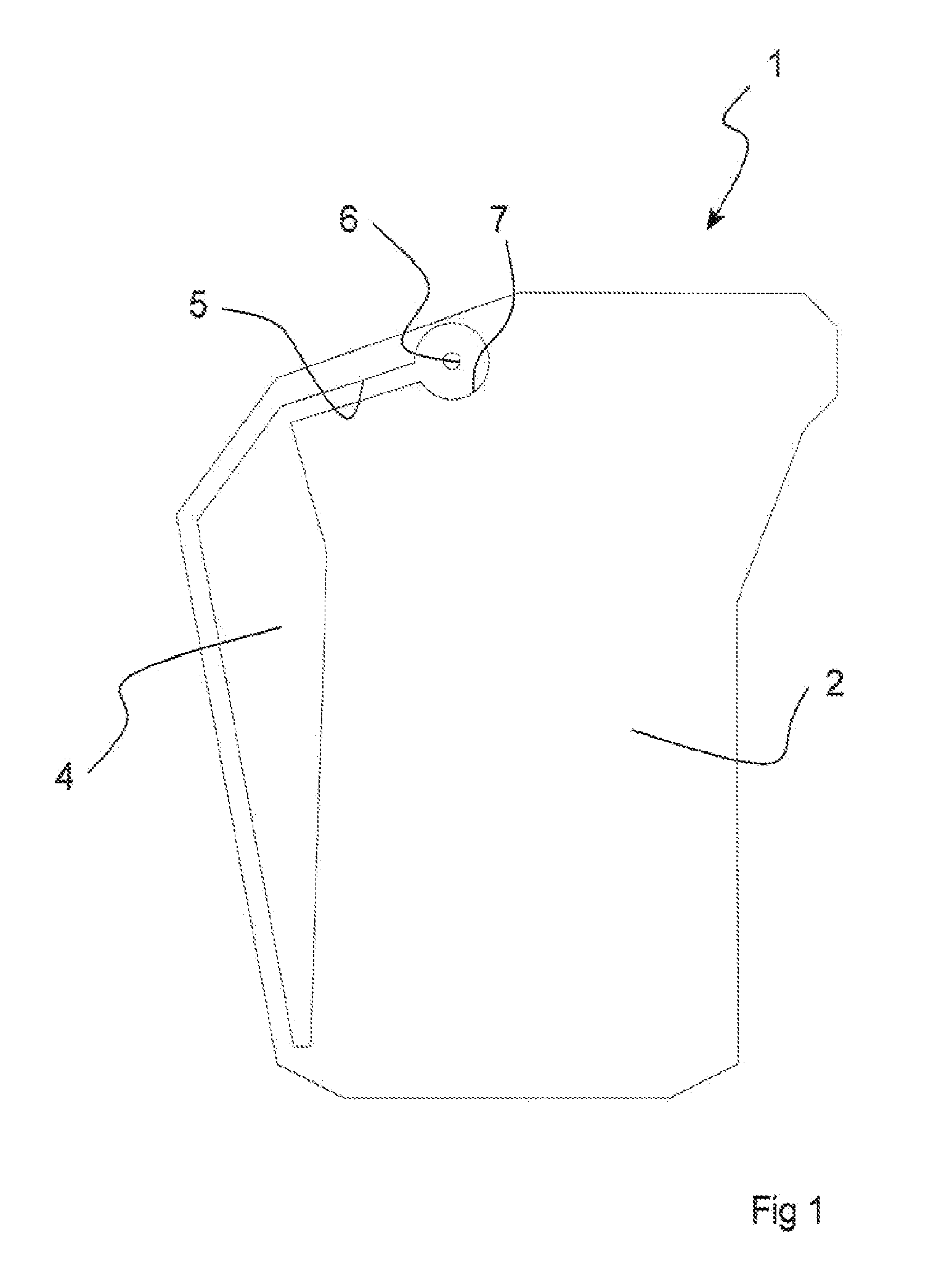
[0020]With reference to FIG. 1, a container 1 according to the present invention is shown.

[0021]The container 1 is of a collapsible type, which means that its walls are flexible and define a compartment whose volume is dependent on the relative position of the walls.

[0022]The container 1 comprises two opposite side walls 2 and a bottom wall 3 (shown in FIG. 2), which walls 2, 3 are interconnected along a connecting portion for forming of said compartment.

[0023]Furthermore, the two opposite side walls 2 of the container 1 define a handle portion 4, which communicates, via a duct 5, with an opening 6 formed in one of the side walls. Also said duct 5 is defined by said side walls 2. The duct 5 further has a section 7 surrounding said opening 6.

[0024]The handle portion 4 is intended to be filled with gas. By filling it with gas a handle that is easy to grasp is obtained, but also a container 1 with increased stability.

[0025]When filled with gas the duct 5 has a cross-sectional area that...


PUM

PropertyMeasurementUnit
flexibleaaaaaaaaaa
volumeaaaaaaaaaa
speedaaaaaaaaaa

Abstract

A method for gas filling a handle portion of a container of a collapsible type. The handle portion being defined by two opposite side walls of the container and communicating, via a duct defined by the side walls, with an opening formed in one of the side walls. The method including the steps of supplying, at a gas filling station, a gas to the handle portion via the opening and the duct, blocking the duct by a squeezing action to retain the gas supplied to the handle portion, transporting the container to a sealing station while maintaining the squeezing action and, at said sealing station, sealing the duct while maintaining the squeezing action, so as to permanently enclose the gas in the handle portion. The disclosure further concerns a container of a collapsible type.

Description

TECHNICAL FIELD[0001]The present invention relates to a method for gas filling a handle portion of a container of a collapsible type. More specifically, the invention concerns a method for gas filling a handle portion which is defined between the side walls of the container and which communicates with an opening formed in one of the side walls via a duct defined between the side walls.BACKGROUND ART[0002]Many different types of container to be filled with products in the form of liquid or powder are currently available. Increasingly, containers of a collapsible type are being used. By a container of a collapsible type is meant a container having a compartment which is defined by flexible walls and whose volume is dependent on the relative position of the walls and, thus, dependent on the filling ratio of the container.[0003]This type of containers may have a number of different handle types.[0004]EP 1 667 917 discloses a container of a collapsible type, which has a handle portion in...

Claims


Application Information

Patent Timeline
Patent Type & Authority Patents(United States)
IPC IPC(8): B65B61/14B31B50/86
CPCB31B19/86B65B61/14B31B2219/909B31B70/872B65D33/06B31B50/86B65D75/56B65D33/065B65D75/008
Inventor GUSTAFSSON, PER
Owner ECOLEAN
Learn More