System and method for detection and repair of pulmonary air leaks

a technology for pulmonary air leakage and pulmonary artery, which is applied in the field of detection and repair of pulmonary air leakage, can solve the problems of increasing morbidity and mortality, persistent air leakage, and dramatically increasing the length of hospital stay

Active Publication Date: 2012-05-22
FRIEDBERG JOSEPH S
View PDF6 Cites 15 Cited by
  • Summary
  • Abstract
  • Description
  • Claims
  • Application Information

AI Technical Summary

Problems solved by technology

Persistent air leaks after lung surgery such as thoracentesis, lung biopsy or intercostal analgesic rib blocks are serious complications that result in increased morbidity and mortality as well as dramatically increased length of hospital stay.
Air leaks following pulmonary procedures usually are due to incomplete apposition of the pulmonary parenchyma following resection.
Persistent air leaks, which are those that fail to resolve within one week, are the most frequent complication in patients undergoing general thoracic procedures.
A prolonged air leak can result in a broncho-pleural fistula—a nonhealing, abnormal communication between the lung and the chest cavity.
The patients who are predisposed to these problems, either spontaneously or iatrogenically, frequently have underlying medical problems (especially pulmonary) that make aggressive intervention a hazardous proposition.
Prolonged air leaks can even result in patient death.
Air leaks are the most frequent cause of extended hospital stay after thoracic surgery and results in significantly increased patient morbidity and hospital costs.
Detecting the location of an air leak is in and of itself a difficult problem.
These modalities offer varying levels of reliability and satisfaction but are not consistently sensitive and accurate.
This valve allows air leaking from the lung to escape from the chest cavity but does not allow air to enter and subsequently collapse the lung.
This technique has the shortcoming that the leak is not easy to localize if the leak is not from a readily visualized surgical bronchial stump.
In addition, this can cause pneumonia and respiratory failure.
Unlike a tire, however, the lung is a complexly shaped organ and it is frequently difficult, even with a major operation, to localize all leak sites.
These products can only be applied to the outside of the lung in the setting of a major operation where the patient is under general anesthesia with selective lung ventilation.

Method used


Image

  • System and method for detection and repair of pulmonary air leaks
  • System and method for detection and repair of pulmonary air leaks
  • System and method for detection and repair of pulmonary air leaks

Examples


Embodiment Construction

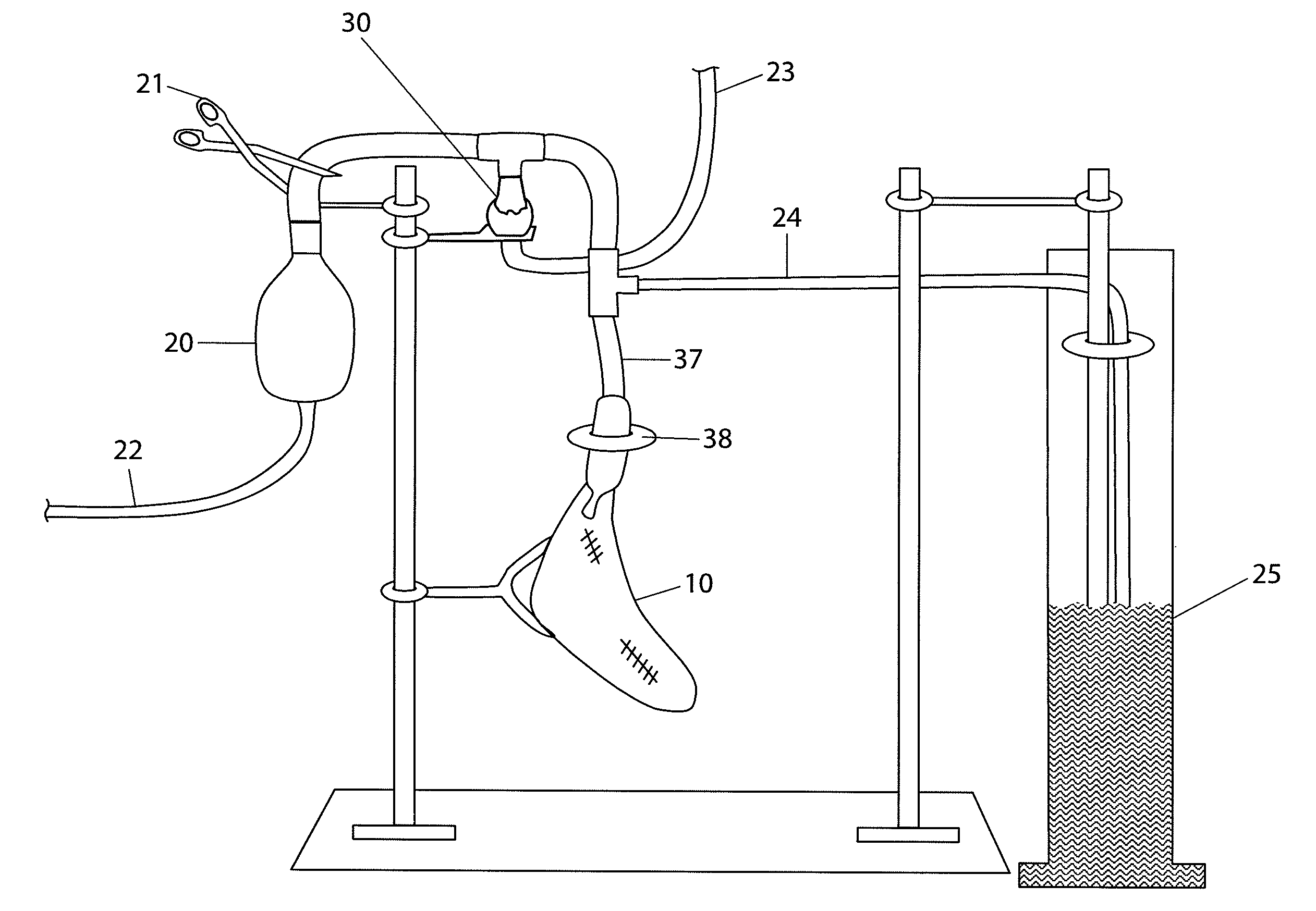
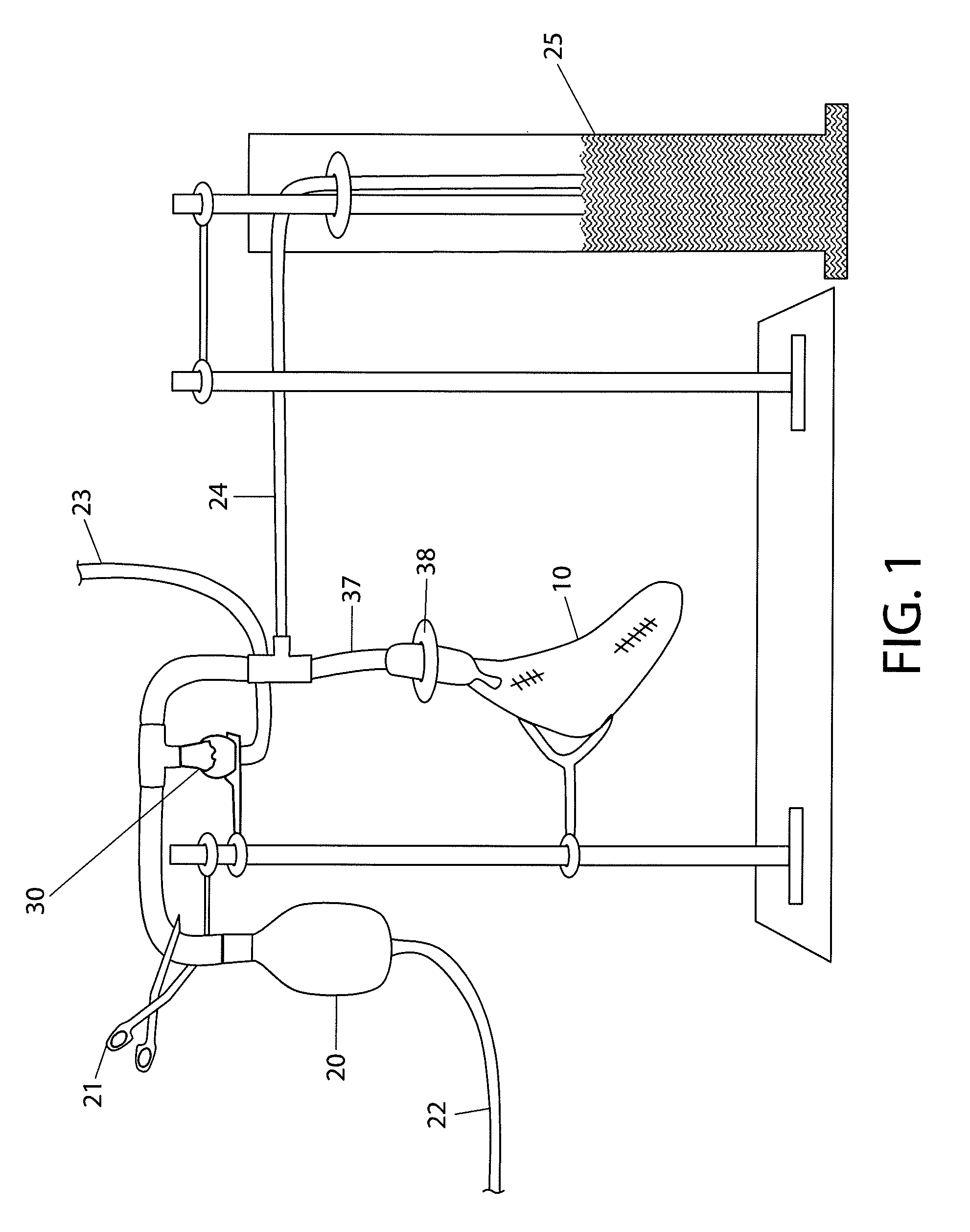
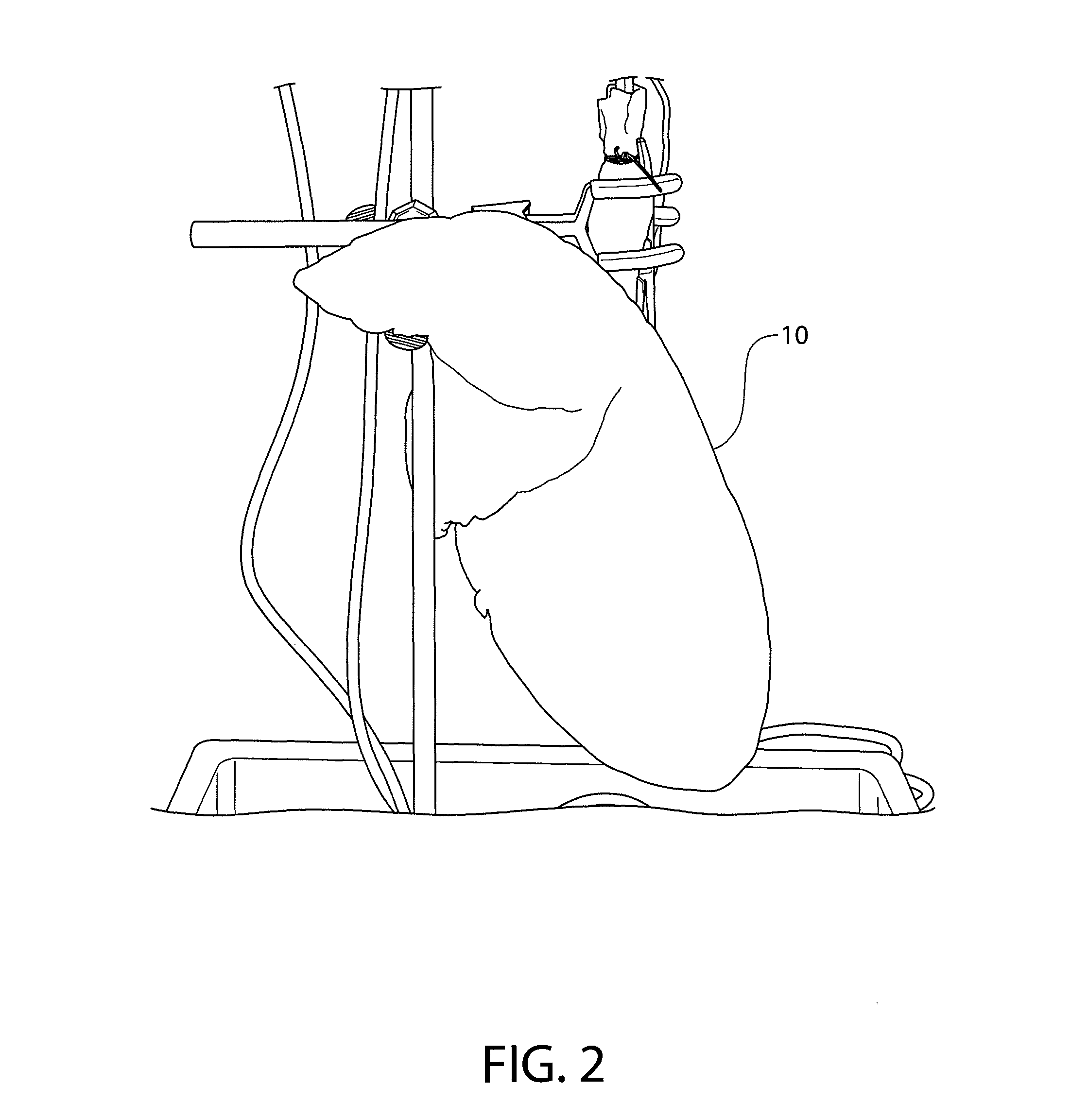
[0020]In one embodiment, a biphasic air leak sealing system is used to seal air leaks, without surgery, by importing into the lung a liquid that follows the path of the escaping gas. The liquid finds the leaks because those are the only areas with any air flow. This does not require the operator to find the leaks. The same premise is also used to find air leaks by using a tracer liquid, which also follows the path of the escaping gas.

[0021]An exemplary leak sealing system comprises two components: a prosealant and an activator. The prosealant can be a building block compound that remains liquid until cross-linked or coagulated by the activator. With a chest tube that is inserted into the patient's chest cavity on suction, the prosealant is introduced into the air stream in a nebulized form. The liquid selectively accumulates at all leak sites. Because the prosealant does not seal by itself, the lung passageways are not blocked and the sealant collects only at the site of the air lea...


PUM


Abstract

A method for repairing pulmonary air leaks in a lung residing in a chest cavity and having an intake air stream and an outer surface is disclosed. An exemplary method comprises: introducing a first component of a biphasic sealant component as a liquid into the intake air stream of the damaged lung; ensuring that there is a pressure differential between the intake air stream and the outer surface of the lung; and introducing a second component of a biphasic sealant component into the chest cavity. The first sealant component collects at the air leak site and forms a sealant in combination with the second sealant component.

Description

FIELD OF INVENTION[0001]This invention relates to the detection and repair of pulmonary air leaks.BACKGROUND OF THE INVENTION[0002]Persistent air leaks after lung surgery such as thoracentesis, lung biopsy or intercostal analgesic rib blocks are serious complications that result in increased morbidity and mortality as well as dramatically increased length of hospital stay. Air leaks can also occur spontaneously in a number of diseases. Most spontaneous air leaks result from rupture of blebs located at the apex of the lung. Air leaks following pulmonary procedures usually are due to incomplete apposition of the pulmonary parenchyma following resection. Fifteen percent of all patients undergoing pulmonary procedures develop air leaks and some studies have shown a prevalence as high as fifty-eight percent following lobectomy. Persistent air leaks, which are those that fail to resolve within one week, are the most frequent complication in patients undergoing general thoracic procedures....

Claims


Application Information

Patent Timeline
Patent Type & Authority Patents(United States)
IPC IPC(8): A61M11/00A61M37/00
CPCA61B5/415A61B5/418A61B17/00491A61B17/0057A61B5/08A61B2017/00641
Inventor FRIEDBERG, JOSEPH S.
Owner FRIEDBERG JOSEPH S
Why Eureka
Try Eureka