
Dual braided catheter shaft

a technology of catheter shaft and braided shaft, which is applied in the direction of catheters, intravenous devices, etc., can solve the problems of limiting the designer's ability to reducing the size of the lumen that is available, and reducing so as to reduce the inner diameter of the shaft, reduce the size of the lumen, and optimize the inner coil design

Active Publication Date: 2012-05-22
ST JUDE MEDICAL ATRIAL FIBRILLATION DIV
View PDF13 Cites 24 Cited by
  • Summary
  • Abstract
  • Description
  • Claims
  • Application Information

AI Technical Summary

Benefits of technology

The present invention provides an improved construction process and catheter shaft that overcomes the disadvantages of conventional processes. The invention allows for the use of flat wires for the inner braid, which enhances design flexibility and potentially reduces the size of the shaft. The invention also allows for the formation of a continuous flow process for the shaft, reducing construction complexity and costs. The invention also minimizes air pockets in the finished shaft. The catheter shaft can be formed with varying mechanical properties along its length. The invention also provides a method for constructing a dual braided shaft with improved integration of the inner braid. Overall, the invention provides a more efficient and effective catheter shaft construction process.

Problems solved by technology

It has been recognized that there are a number of disadvantages associated with this dual braided catheter construction process and the resulting product.
This limits the designer's ability to optimize the inner coil design and, specifically, tends to reduce the inner diameter of the shaft, thereby reducing the size of the lumen that is available for wiring, irrigation and the like.
This increases the difficulty of construction and associated costs.
Moreover, the reflow process may not result in the inner braid being fully embedded in the polymer.
That is, small air pockets may remain between the coil and the polymer, which can adversely affect the mechanical properties of the coil / polymer system.
Using the conventional processes, it is also difficult to construct a catheter shaft having varying properties along its length.
However, it is generally impractical to attempt to vary the material extruded in a continuous process to the desired accuracy.
However, because the shaft is not formed in a continuous flow process, such construction is slow and expensive.

Method used


Image

  • Dual braided catheter shaft
  • Dual braided catheter shaft
  • Dual braided catheter shaft

Examples


Embodiment Construction

[0022]In the following description, the invention is set forth in the context of certain examples of a dual braided catheter shaft and associated construction processes. While these examples illustrate certain advantageous implementations of the present invention, the invention is not limited to the specific examples described below. Accordingly, the following description should be understood as exemplifying the invention and not by way of limitation.

[0023]FIG. 4 shows and electrode catheter 400 that may employ a catheter shaft 406 constructed in accordance with the present invention. Generally, the catheter 400 includes a handle set 402, an electrode tip 404 and the catheter shaft 406 that extends between the handle set 402, at the proximal end of the catheter shaft 406, and the electrode tip 404 at the distal end of the catheter shaft. The catheter 400 may include other components such as steering mechanisms, irrigation components and the like that are omitted from the drawing for...


PUM


Abstract

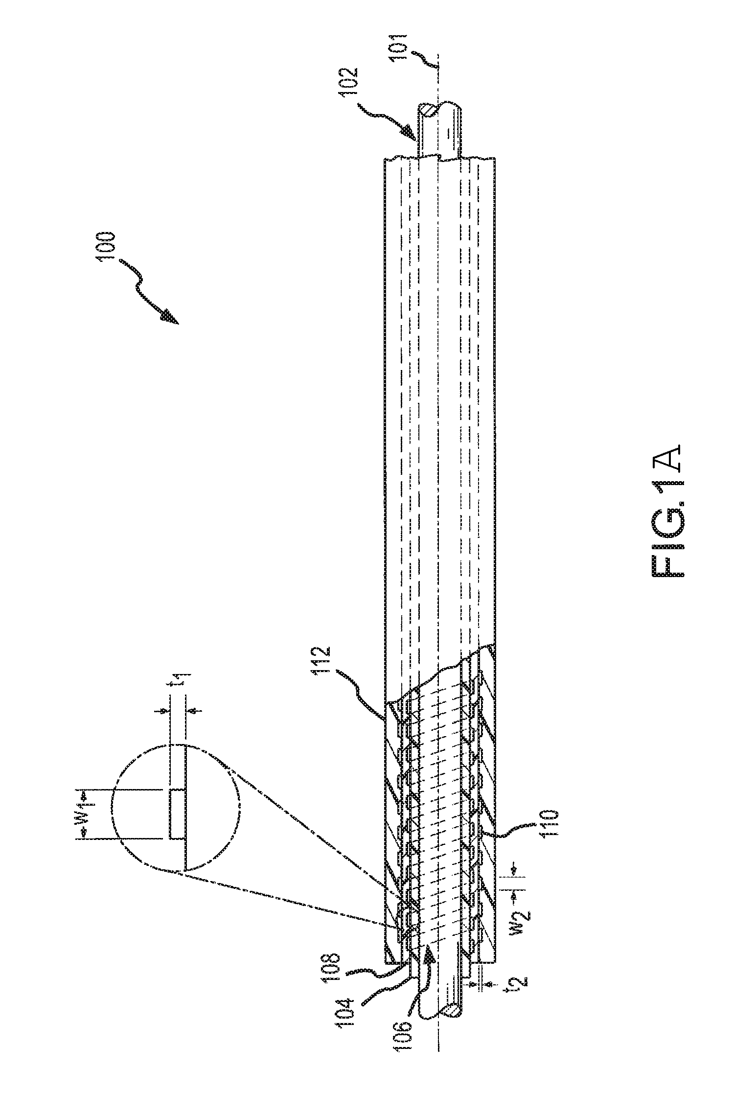
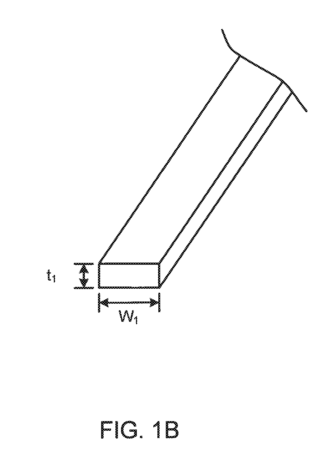
A dual braided catheter shaft includes a flat wire forming the inner braid, thereby potentially allowing for reduced radial thickness of the shaft. In one embodiment, the shaft (100) includes an inner polymer jacket (104), an inner braid (106) formed on the inner jacket (104), an intermediate jacket (108) formed over the inner braid (106), an outer braid (110) formed on the intermediate jacket (108) and an outer jacket (112) formed on the outer braid (110). A preferred construction process involves extruding polymer material directly onto each of the inner and outer braids (106 and 110) so that little or no air gaps remain between the polymer material and the braids (106 and 110). The braiding parameters of the inner and outer braids (106 and 110) can be varied along the length of the catheter to provide varying mechanical properties.

Description

BACKGROUND OF THE INVENTION[0001]a. Field of the Invention[0002]The present invention relates generally to catheter shafts and, in particular, to a dual braided shaft with a reduced thickness that can be constructed with reduced reflowing of polymers.[0003]b. Background Art[0004]Catheters are typically threaded through a blood vessel of a patient to reach a desired site for a medical procedure. For example, in the diagnosis and treatment of atrial fibrillation, a catheter may be routed through a vessel from a patient's leg or neck to access chambers of a patient's heart. Electrodes at the distal end of the catheter can then be used for a variety of purposes including electrical mapping and ablation. The catheter therefore may include one or more internal lumens to accommodate electrode wiring and steering wires, as well as to permit irrigation as may be useful for certain procedures.[0005]The catheter body or shaft is therefore designed with a number of objectives in mind. First, th...

Claims


Application Information

Patent Timeline
Patent Type & Authority Patents(United States)
IPC IPC(8): A61M25/00
CPCA61M25/0012A61M25/005A61M25/0054A61M25/0053A61M2025/0059
Inventor STEHR, RICHARD E.TEGG, TROY T.JOHNSON, MICHAEL J.FUENTES, ALLAN M.
Owner ST JUDE MEDICAL ATRIAL FIBRILLATION DIV
Learn More