Control device

a control device and heat radiation sheet technology, applied in the direction of electrical equipment construction details, furniture parts, lighting and heating apparatus, etc., can solve the problems of reducing the heat radiation area of the sub-module, affecting so as to improve the heat radiation ability of the sub-module and increase the heat radiation area of the electronic parts.

Active Publication Date: 2012-05-22
HITACHI LTD
View PDF82 Cites 27 Cited by
  • Summary
  • Abstract
  • Description
  • Claims
  • Application Information

AI Technical Summary

Benefits of technology

[0008]To solve the above problems, the present invention is to provide a control device capable of increasing the heat radiating area of the electronic parts mounted to the sub-module and improving the heat radiation ability of the sub-module.
[0010]The present invention is capable of increasing the heat radiating area of the electronic parts mounted to the sub-module and improving the heat radiation ability of the sub-module.

Problems solved by technology

In conventional control device with a heat radiating structure using heat radiation sheets shown in FIG. 5, the thickness of the heat radiation sheet possible to be inserted between the electronic parts and a housing cover is limited from a view point of electronic parts dimensional accuracy.
Also, even if inserting the heat radiation sheet by suppressing the thickness of the heat radiation sheet capable of inserting it, repellent force of the heat radiation sheet presses the electronic parts and therefore, the electronic parts will have bad influences.
Particularly, a control device accommodating the sub-module mounting different shaped electronic parts such as coils and capacitors in a housing cover fails to assure sufficient contact area corresponding to the heat radiation sheets without supplying a surplus repellent force to the mounted each electronic parts.

Method used


Image

  • Control device
  • Control device
  • Control device

Examples


first embodiment

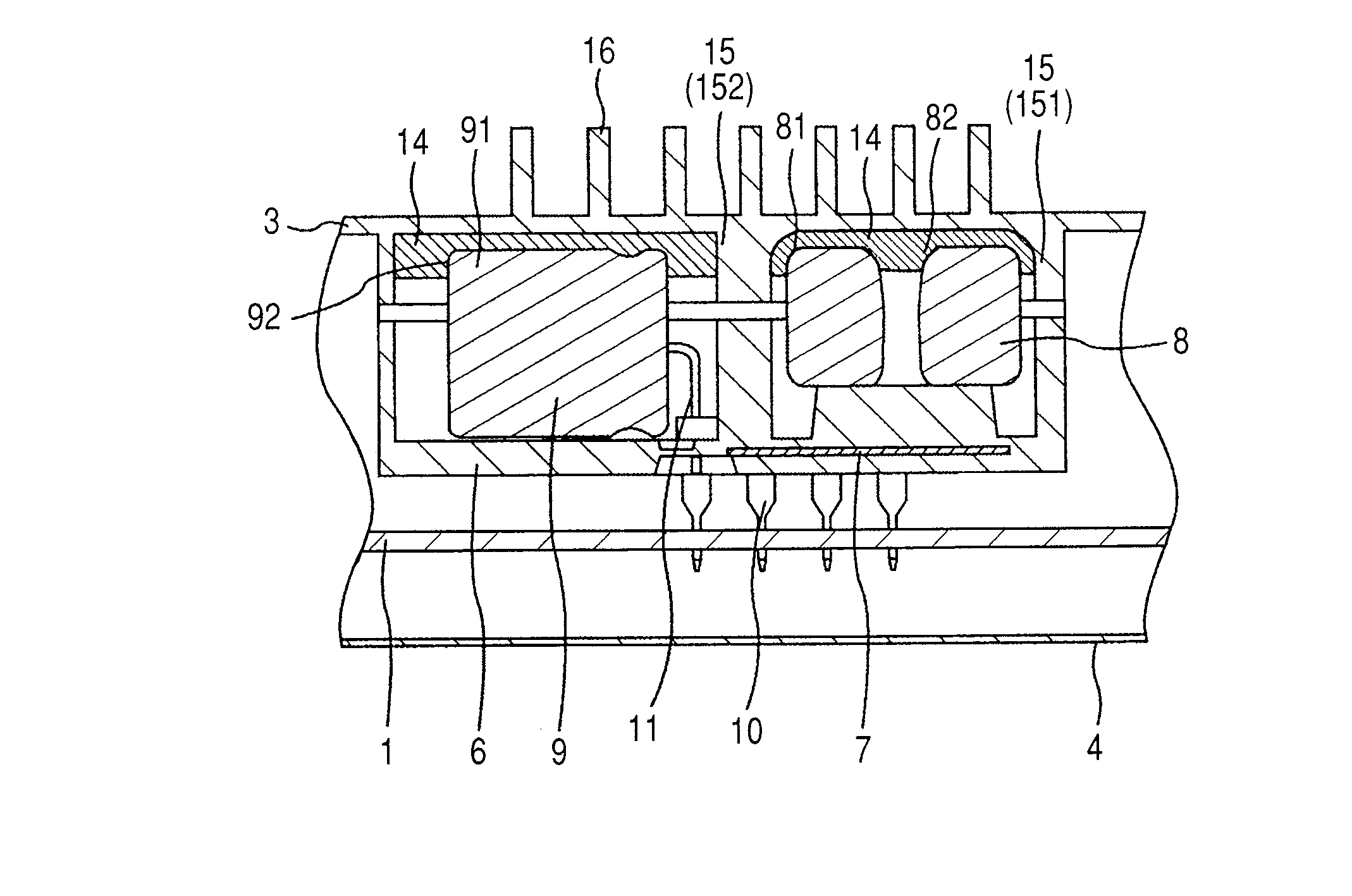
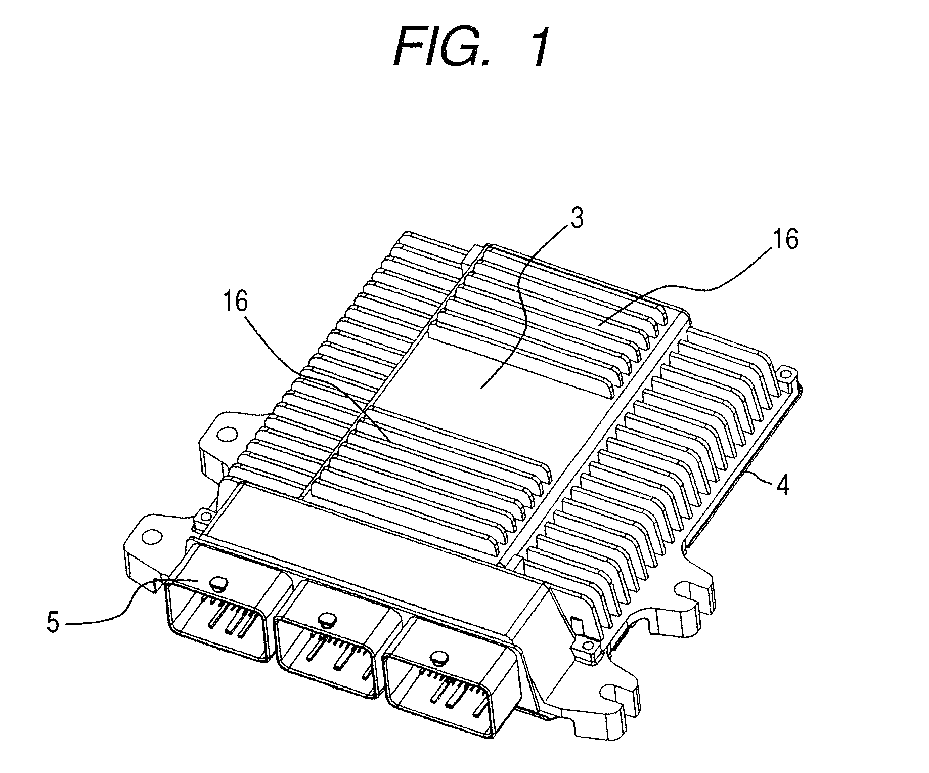
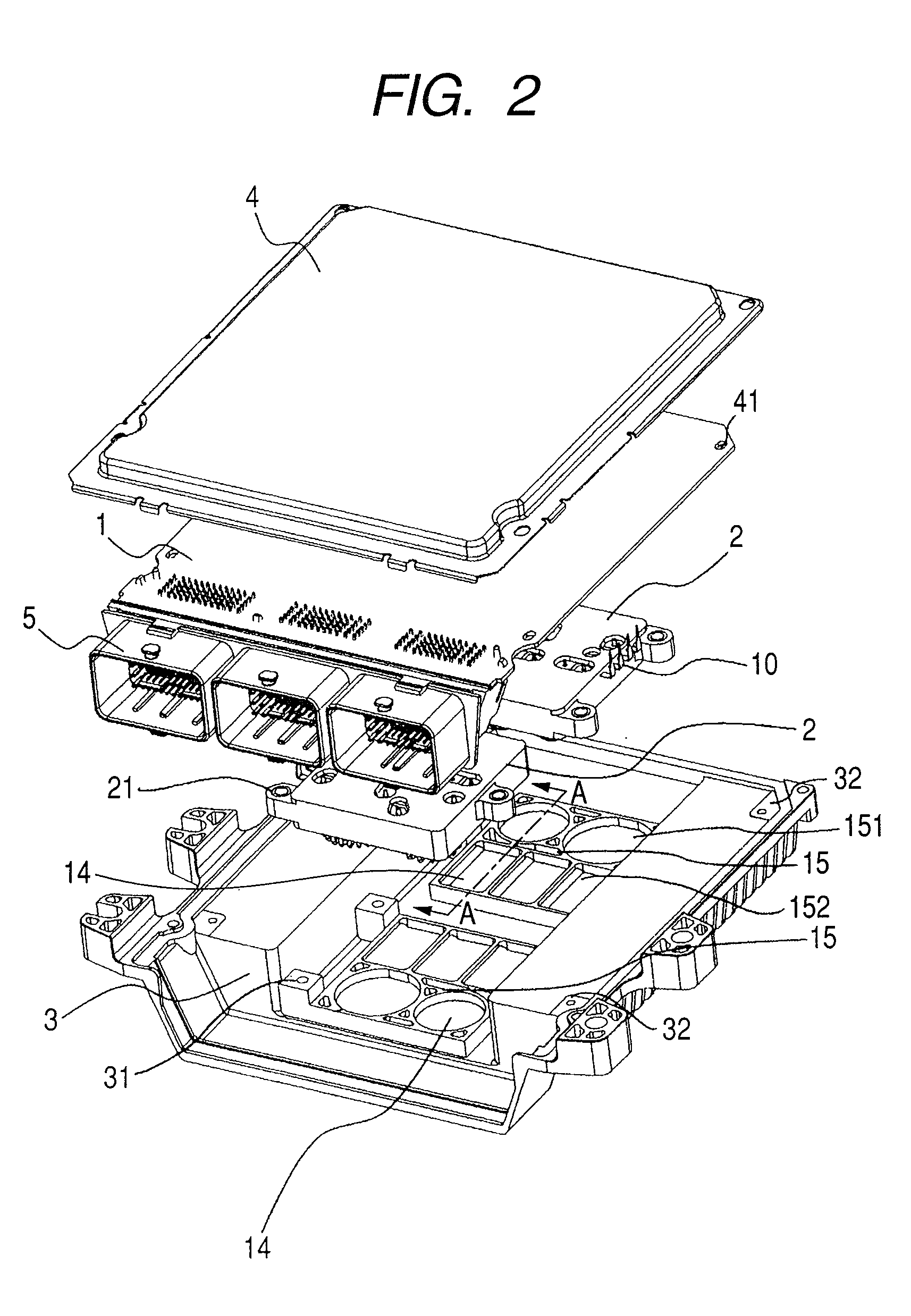
[0017]FIG. 1 is a perspective view showing a control device in accordance with the invention. FIG. 2 is an exploded perspective view showing the control device shown in FIG. 1. FIG. 3 is an enlarged section view showing the control device along a line A-A as shown in FIG. 2. FIG. 2 is drawn being turned upside down comparing with FIGS. 1 and 3.

[0018]As shown in FIGS. 1 to 3, the control device as a module has a control board 1 mounting chips (electronic elements) such as a microcomputer and connectors 5 acting as an external interface, a sub-module 2 mounting electronic parts 8 and 9 in a sub-module case 6, a housing cover accommodating the control board 1 and the sub-module 2, and a housing base 4.

[0019]In the control device, the sub-module 2 is accommodated and fixed in a space of the housing cover 3, and the control board 1 is also fixed to the housing cover 3. Moreover, the housing cover 3 fixing the control board 1 and sub-module 2 is fastened to the housing base 4.

[0020]As sho...

second embodiment

[0041]A second embodiment is explained hereinafter.

[0042]FIG. 4 is a sectional view showing an essential part of a control device of the present embodiment. The basic constituting part of the control device of the present embodiment is nearly same as that of the control device shown in FIG. 1 to FIG. 3, therefore, same reference numbers are given to the same portions. The control device differs from the first embodiment from a viewpoint of the constitution forming the accommodation portion 18 on the base 4 and radiating heat of the capacitors 9 of the sub-module from both sides of the housing cover 3 and the housing base 4.

[0043]The control device of the embodiment has a heat sink member 17 between the control board 1 and the sub-module 2. The heat sink member 17 has an accommodation portion 18 similar to the accommodation portion 15 formed on the housing cover 3. The resin case 6 is provided with an opening 22 being under the capacitors 9, and thereby each of the capacitors 9 faces...


PUM


Abstract

A modular control device comprises a control board, a sub-module and a housing cover, with a microcomputer mounted on the control board. The sub-module has a sub-module case provided with a wiring layer that is mounted into a wall of the sub-module case. Electronic parts are mounted in the sub-module case to electrically connect to the control board through the wiring layer. A housing cover accommodates the control board and the sub-module. A housing base is joined with the housing cover. The accommodation portion has a shape corresponding to a shape of each of the electronic parts is arranged in the housing cover. The sub-module is mounted to the housing cover with a heat radiation adhesive between the accommodation portion and each of the electronic parts.

Description

CLAIM OF PRIORITY[0001]This application claims priority from Japanese patent application serial No. 2008-091580, filed on Mar. 31, 2008, the content of which is hereby incorporated by reference into this application.BACKGROUND OF THE INVENTION[0002]The present invention is related to a control device mounted on a vehicle such as automobile, and particularly, to a heat radiating structure of the control device mounting electronic parts with heat generation such as a coil, capacitor or the like.[0003]Recently, a control device mounted on vehicles such as automobiles or the like have a tendency of high power and high functions. Disclosed is a control device in which electronic parts are wired to each other with low resistance wirings by forming the electronic parts such as coils, capacitors, or the like as a sub-module to realize the high power and high functions.[0004]FIG. 5 is an exploded perspective view showing a conventional control device. As shown in FIG. 5, the conventional con...

Claims


Application Information

Patent Timeline
Patent Type & Authority Patents(United States)
IPC IPC(8): H05K7/00F28F7/00H05K1/00H05K7/20A47B81/00
CPCH05K7/026H05K7/20854
Inventor KANEKO, YUJIROASANO, MASAHIKOYOSHINARI, HIDETO
Owner HITACHI LTD
Why Eureka
Try Eureka