
Apparatus and method for monitoring base station signal in communication system having multiple antennas

a communication system and antenna technology, applied in the field of antenna monitoring apparatus, can solve the problems of complex structure of the base station, no prior art related to the application of the monitoring apparatus, etc., and achieve the effects of reducing cost, efficient monitoring, and inexpensive installation

Active Publication Date: 2012-05-22
SAMSUNG ELECTRONICS CO LTD +4
View PDF19 Cites 4 Cited by
  • Summary
  • Abstract
  • Description
  • Claims
  • Application Information

AI Technical Summary

Benefits of technology

The present invention provides a signal monitoring apparatus for a base station in a communication system with multiple antennas. The apparatus includes a transmitting / receiving unit, a radio frequency calibration unit, and a signal monitoring unit. The apparatus can efficiently monitor signals from multiple antennas by sharing an RF calibration apparatus for signal monitoring. The apparatus analyzes signals from target receive and transmit signals to user equipment, and includes means for calibration of the transmitting unit. The technical effect of the invention is to simplify the structure of the base station and improve the efficiency of signal monitoring.

Problems solved by technology

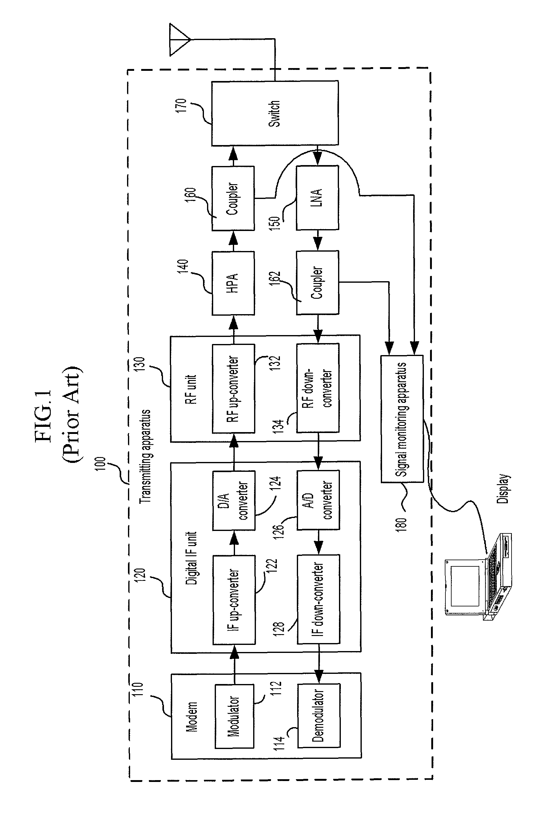
Such a monitoring apparatus has been typically applied to a base station using a single antenna, and thus, there is no prior art related to application of the monitoring apparatus to a system using multiple antennas.
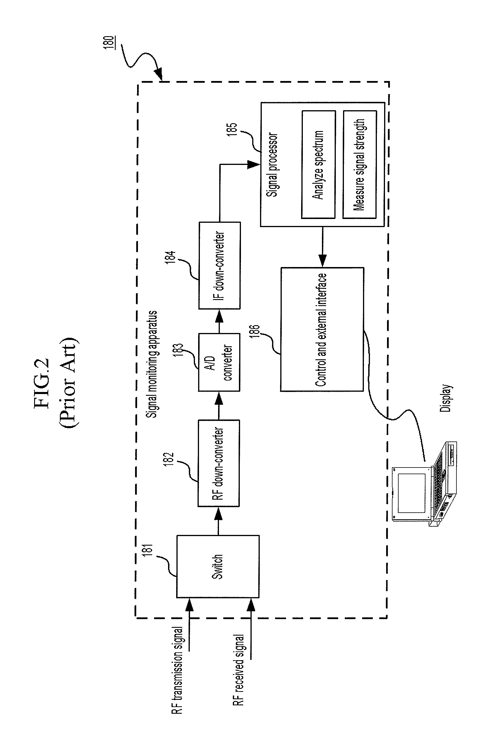
In addition, when the system using the multiple antennas employs the conventional signal monitoring apparatus, the signal monitoring apparatus of FIG. 2 must be provided for each antenna, and accordingly, a structure of the base station becomes complicated.

Method used


Image

  • Apparatus and method for monitoring base station signal in communication system having multiple antennas
  • Apparatus and method for monitoring base station signal in communication system having multiple antennas
  • Apparatus and method for monitoring base station signal in communication system having multiple antennas

Examples


Embodiment Construction

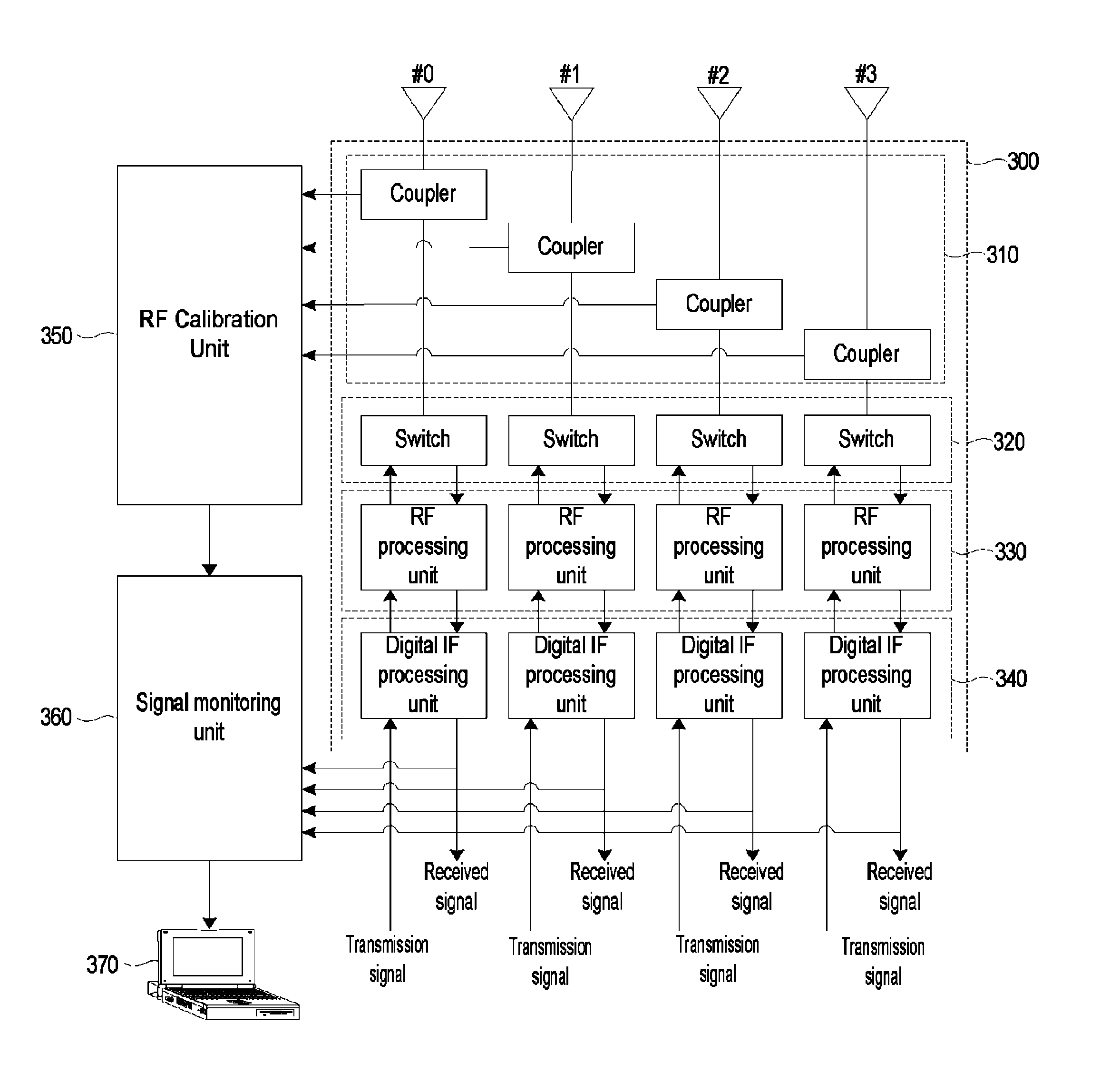
[0030]In the following detailed description, only certain exemplary embodiments of the present invention have been shown and described, simply by way of illustration. As those skilled in the art would realize, the described embodiments may be modified in various different ways, all without departing from the spirit or scope of the present invention. Accordingly, the drawings and description are to be regarded as illustrative in nature and not restrictive. Like reference numerals designate like elements throughout the specification.

[0031]In addition, unless explicitly described to the contrary, the word “comprise” and variations such as “comprises” or “comprising” will be understood to imply the inclusion of stated elements but not the exclusion of any other elements.

[0032]FIG. 3 is a schematic block diagram showing a signal monitoring apparatus of a base station in a communication system having multiple antennas according to an exemplary embodiment of the present invention. In FIG. ...


PUM


Abstract

In a signal monitoring apparatus of a base station of a communication system having multiple antennas, a transmitting / receiving unit transmits a plurality of transmit signals by using the multiple antennas or processes a plurality of receive signals received through the multiple antennas. A radio frequency calibration unit calibrates the transmit signals transmitted through the multiple antennas, and processes at least one target transmit signal among the plurality of transmit signals so as to monitor the at least one target transmit signal. A signal monitoring unit receives at least one first signal or at least one second signal, and transmits the at least one first signal or the at least one second signal to user equipment. The at least one first signal is a signal processed from at least one target receive signal among the plurality of receive signals, and the at least one second signal is a signal processed from the at least one target transmit signal by controlling the radio frequency calibration unit.

Description

TECHNICAL FIELD[0001]The present invention relates to a method for monitoring a base station signal of a communication system using multiple antennas, and an apparatus using the same. More particularly, the present invention relates to a signal monitoring apparatus that can efficiently monitor a base station signal.BACKGROUND ART[0002]A base station and use equipment (UE) in a mobile communication system transmits / receives a signal by using a frequency division duplex (FDD) method or a time division duplex (TDD) method. The FDD method separates the signal into different frequency bands, i.e., a transmit frequency and a receive frequency, and the TDD method uses the transmit frequency and the receive frequency together.[0003]FIG. 1 shows connections between a signal monitoring apparatus and a transmitting unit of a TDD-based base station according to a prior art.[0004]As shown in FIG. 1, a transmitting apparatus 100 of the TDD-based base station includes a modem 110, a digital interm...

Claims


Application Information

Patent Timeline
Patent Type & Authority Patents(United States)
IPC IPC(8): H04H20/67H04W24/00H04W24/08H04W88/08
CPCH04W24/00H04B17/12H04W88/08H04W24/08
Inventor BANG, YOUNG-JOPARK, YOUN-OKLEE, YONG-SU
Owner SAMSUNG ELECTRONICS CO LTD
Learn More