
Method and system to control mechanical lung ventilation

a technology of mechanical lung and ventilation system, which is applied in the direction of inhalators, sensors, combustion processes, etc., can solve the problems of inability to ensure the appropriate tidal volume for proper respiratory support, lack of volume control, and patient discomfort, so as to reduce the chances of secondary problems, reduce the risk of inhalation, and efficiently and safely control the volume delivered

Active Publication Date: 2012-05-29
INTERMED EQUIPAMENTO MEDICO HOSPITALAR
View PDF6 Cites 12 Cited by
  • Summary
  • Abstract
  • Description
  • Claims
  • Application Information

AI Technical Summary

Benefits of technology

"The present invention relates to a method and system for controlling mechanical lung ventilation in patients. The method involves monitoring the volume of air inhaled by the patient during respiratory cycles and controlling the pressure to keep the volume within a safe range. This ensures that patients receive the necessary amount of air and oxygen, while avoiding the risks of inhaling too much or too little. The system includes a ventilation system that efficiently and safely controls the volume delivered to patients, keeping it within a pre-determined range. The method and system can be used in controlled, assisted, or spontaneous respiratory cycles. The invention aims to improve the control of mechanical lung ventilation and provide a safer and more effective respiratory system for patients."

Problems solved by technology

In case of assisted cycles, the controlled volume mode, despite being synchronized with the patient's initial effort, does not allow flow synchronization along the cycle, thus resulting in discomfort for the patient.
On the other hand, the controlled pressure mode allows the patient to modulate the inspiratory flow, but does not ensure the resulting tidal volume is appropriate for proper respiratory support.
Also in this case, the lack of control over the volume is a critical point, especially in patients at the initial phase of being weaned off ventilator support.

Method used


Image

  • Method and system to control mechanical lung ventilation
  • Method and system to control mechanical lung ventilation
  • Method and system to control mechanical lung ventilation

Examples


Embodiment Construction

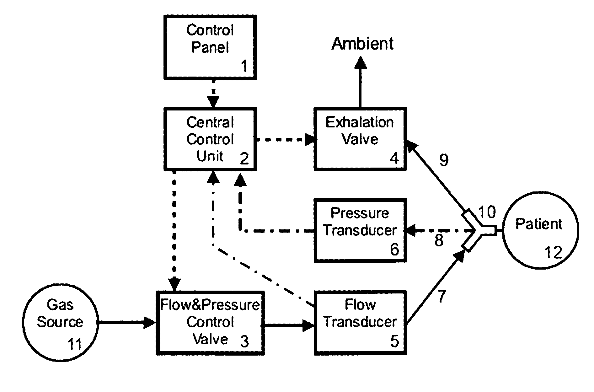
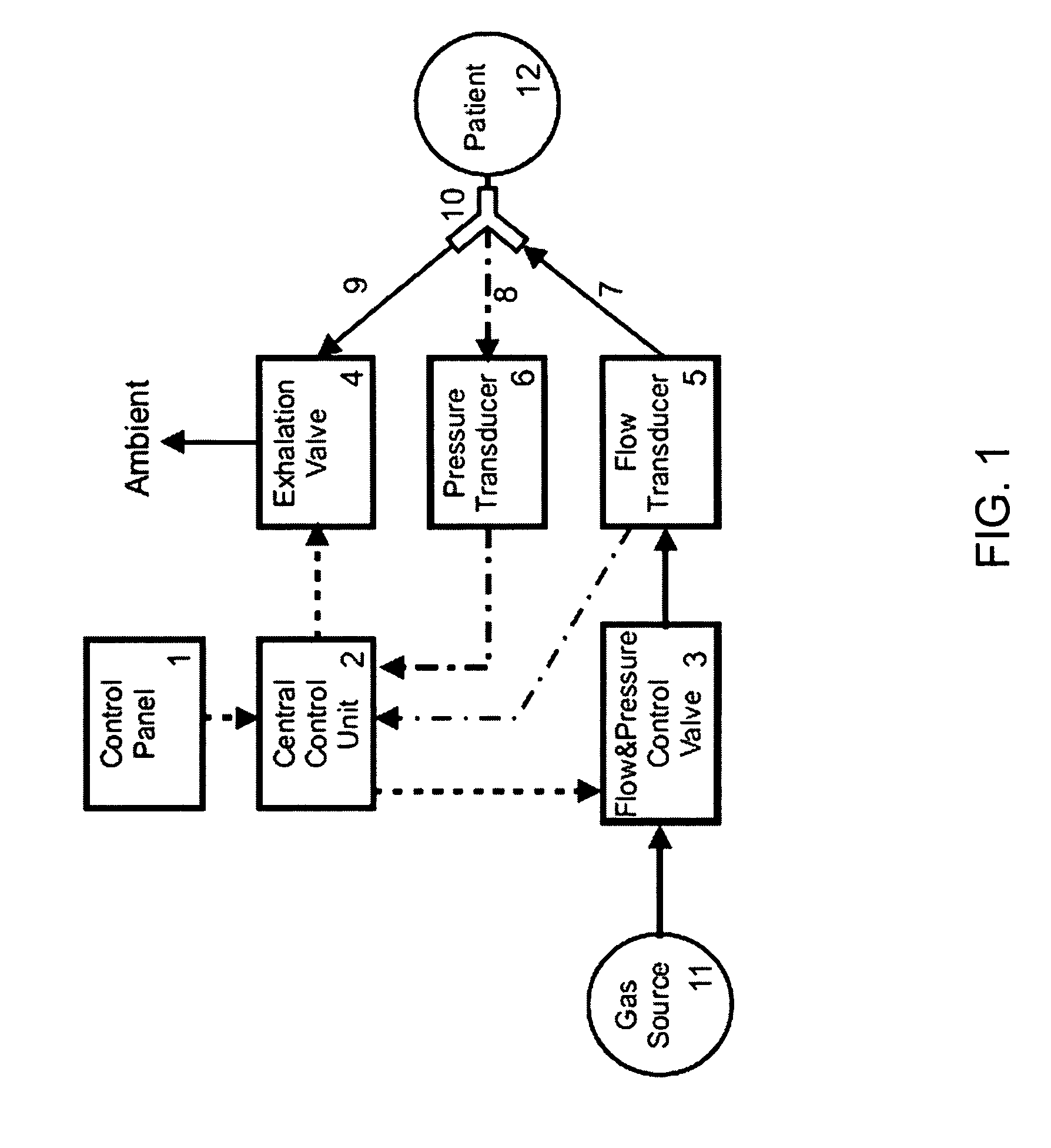
[0083]FIG. 1 schematically shows an embodiment of a ventilator system of the type as contemplated by the control system of the present invention, comprising a flow and pressure control valve 3 as connected to a source of gas 11, controlling the inspiratory flow by means of an inspiratory tube 7 connected to the patient 12 by means of a “Y” type connector 10. From the patient 12, the gas is exhaled through an exhalation tube 9 connected to the other end of the “Y” connector 10, according to the control of an exhalation valve 4. The pressure in the airway of the patient is sent from the “Y” connector 10 which is connected to a pressure transducer 6 through a tube 8.

[0084]The inspiratory flow is measured by the flow transducer 5 located downstream from the flow and pressure control valve 3. Both inspiratory flow and airway pressure signals, coming from flow transducer 5 and pressure transducer 6, jointly with parameters adjusted by the control panel 1, are used by the central control u...


PUM


Abstract

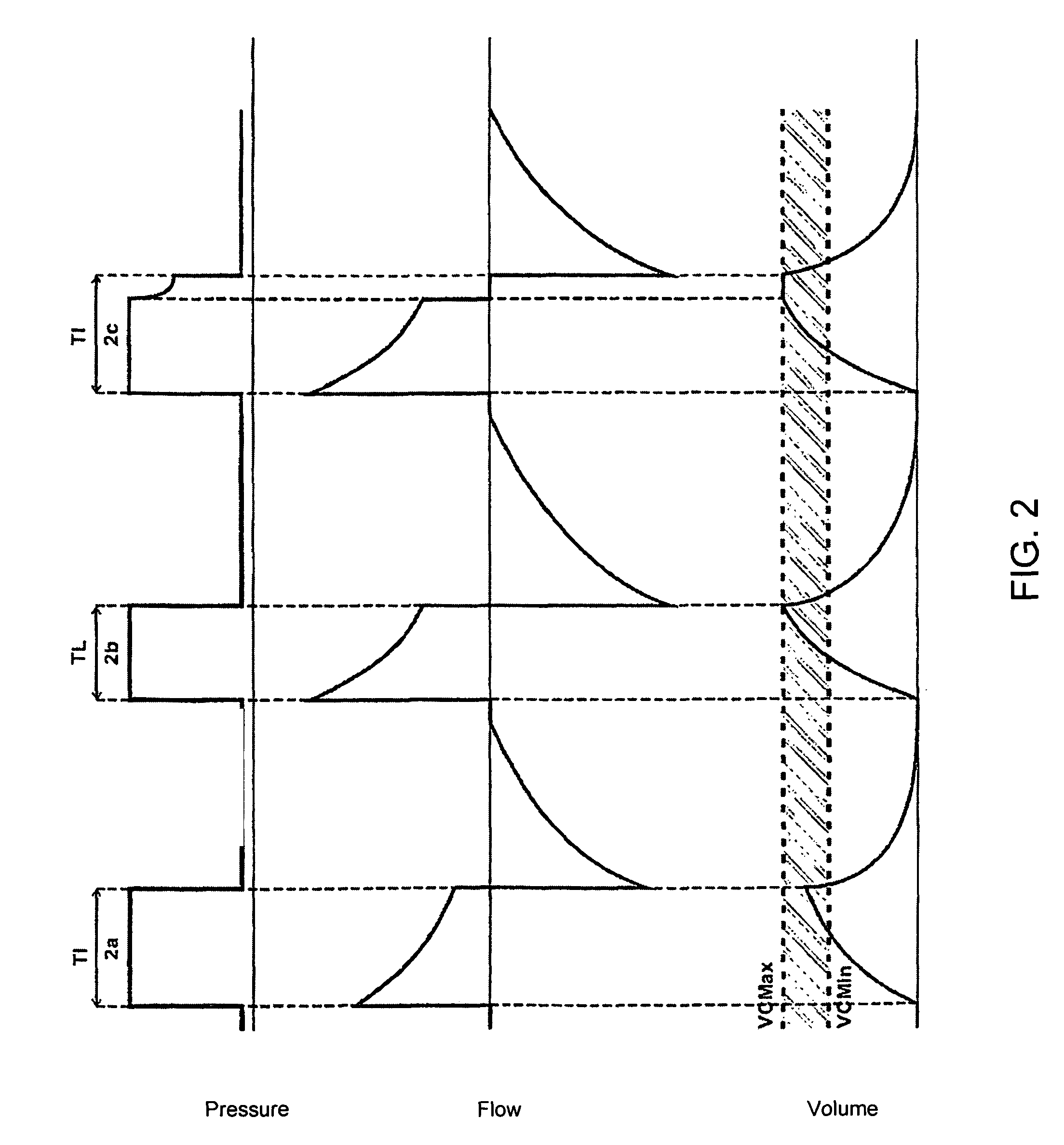
The present disclosure refers to a system to control mechanical lung ventilation with volume band, more particularly a system to manage respiratory cycles in patients. Preferably, said respiratory cycles are controlled under pressure, so that the volumes as inspired by the patient are maintained within a volume range, comprising a lower volume limit and an upper volume limit, which are previously determined.

Description

CROSS-REFERENCE TO RELATED APPLICATIONS[0001]This Application claims priority under 35 USC §119(a) to Brazilian Patent Application Number PI 0705091-7 filed on Nov. 1, 2007, which is incorporated by reference herein in its entirety.BACKGROUND OF THE INVENTION[0002]Patients requiring artificial ventilation are usually connected to lung ventilators administering in cycles, by means of positive pressure, tidal volumes of a mixture composed by air and oxygen. In an acute respiratory failure condition, the patient is usually sedated or in apnea state, i.e. there is no breathing effort and mechanical ventilation is made by means of controlled cycles.[0003]Controlled cycles may usually be volume controlled or pressure controlled. Volume controlled cycles present a fixed flow pattern and any change in the respiratory mechanics results in change of the pressure in the patient's airway. Controlled pressure mode, on the other hand, keeps pressure in the patient's airway constant, presenting fr...

Claims


Application Information

Patent Timeline
Patent Type & Authority Patents(United States)
IPC IPC(8): F23D11/00F23D14/00
CPCA61M16/00A61M16/0051A61M16/0833A61M16/0858A61M16/204A61M16/205A61M2016/0021A61M2016/0027A61M2016/0039A61M16/024
Inventor BONASSA, JORGE
Owner INTERMED EQUIPAMENTO MEDICO HOSPITALAR
Learn More