Fluid injection device

a technology of fluid injection and injection device, which is applied in the direction of functional valve types, sealing/packing, and borehole/well accessories, etc., can solve the problems of reducing the life of the valve device, reducing the performance, and the known gas lift valve will not work as expected, so as to achieve less pressure loss and large flow area

Active Publication Date: 2012-05-29
GASOLINEEUM TECH
View PDF48 Cites 17 Cited by
  • Summary
  • Abstract
  • Description
  • Claims
  • Application Information

AI Technical Summary

Benefits of technology

[0019]According to yet another embodiment the outer housing and or the internal body may comprise several separable elements connected by for instance threaded joints. This gives the possibility to replace for instance the element of the outer housing comprising the valve seat without having to replace the whole housing.
[0020]The injection device of the present invention may also be positioned in a hydraulic spool piece in relation to a Christmas tree as mentioned above. The spool piece may be formed as a flange and comprise a main bore, in which main bore the injection device may be positioned. There may also be additional side bores for adding of hydraulic fluid and possible venting. The side bores may be adapted to be in communication with at least one opening in the outer housing of the injection device, in order to add hydraulic fluid for operation of the device. Such a system will be equipped with additional sealing elements in appropriate places and a skilled person will understand this. The device may also comprise a pretension means to set the device, i.e. the valve to a given position when hydraulic pressure is not present through the opening, for instance a closed position. The pretension device may be an elastic element such as spring or other pretension means. These features of the invention will provide a device where the flow path of the injection fluid is substantially less tortuous than other known gas injection valves due to the more direct flow through the bore in the internal body and directly out through the slots of the valve. This also gives less pressure losses across the valve. The present invention is also a device with few elements, compared with the majority of other known injection valves. This gives a more reliable device as well. The present invention also has a relatively large flow area through the device; compared with the majority of other known injection valve of similar size.

Problems solved by technology

After a period of time, known gas lift valves will have a tendency of not working as expected.
One problem might be the erosion of the sealing surfaces of the valve device which lead to leakage across the valve seat and reduced performance and a reduced lifetime for the valve devices.
This creates a problem for operation of the well with increased down time, maintenance time and an increased safety hazard.

Method used


Image

  • Fluid injection device
  • Fluid injection device
  • Fluid injection device

Examples


first embodiment

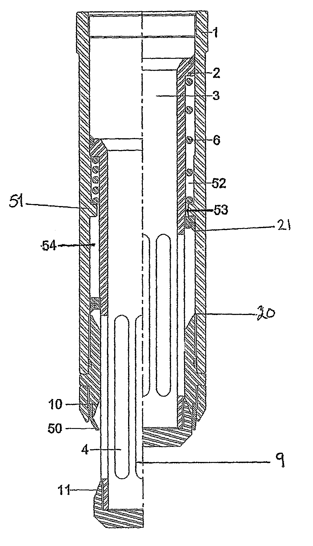
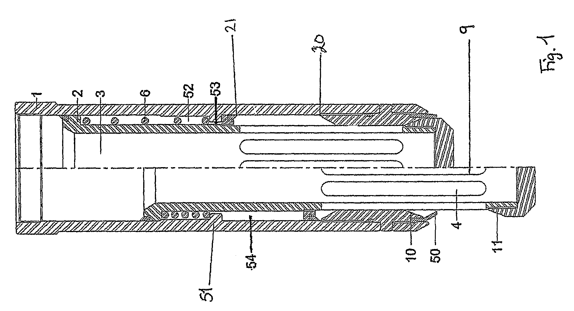
[0024]In FIG. 1 there is shown a device according to the invention. A skilled person will understand how to position the valve device within a well stream and this is therefore not described in this application.

[0025]In FIG. 1 the device comprises an outer housing 1, which is formed from several elements, with an internal body 2 movable within the outer housing 1 between two positions, an open position shown to the left in the figure and a closed position shown in the right half of the figure. The internal body 2 is movable in the longitudinal direction of the internal body 2 and outer housing 1. The outer housing 1 comprises an injection fluid inlet at one end of the outer housing 1 connected to a source of injection fluid (not shown). The injection fluid is transferred through an internal void of the outer housing 1 to an internal bore 3 of the internal body 2. The bore 3 stretches in the longitudinal direction of the internal body 2. The injection fluid will thereafter in an open...

second embodiment

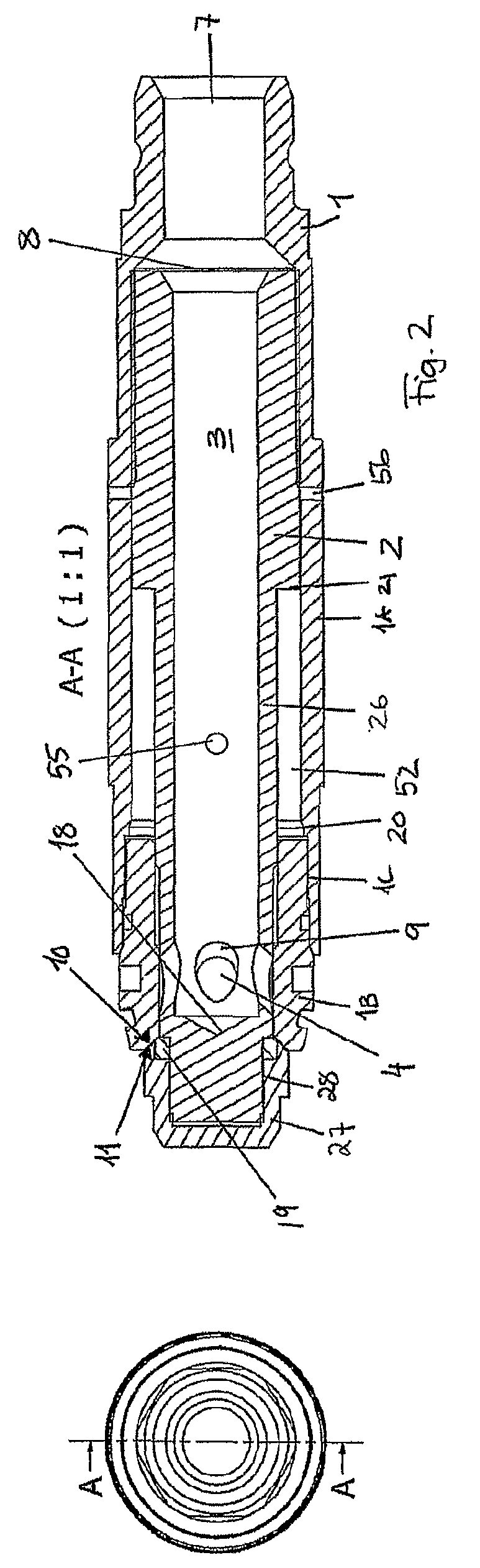
[0029]In FIG. 2 there is shown the device comprising an outer housing 1 and an internal body 2 movable within the outer housing 1. The outer housing 1 has an inlet 7 for the fluid entering the valve device, and there may in relation to this inlet also be positioned an orifice 8 to regulate the flow through the device, to for instance give the flow a rotating flow pattern. The outer housing 1 comprises a first part 1A and a second part 1B comprising the valve seat surface 10, which two parts 1A, 1B are connected by a threaded connection 1C. The outer housings second part 1B also comprises a stop surface 20. There are also an aerating opening 56 in the outer housing to prevent any trapped fluid between the internal body 2 and the outer housing 1 from stopping the movement between the internal body 2 and the outer housing 1, this opening 56 may also be connected to a source of hydraulic fluid to operate the device between a closed and an open position. In such a configuration there wil...


PUM


Abstract

The present invention regards a device designed for injection of fluids in a well bore, typically an offshore well bore for petroleum production and gas injection/gas lift system for fluid injection. The device comprises a outer hollow housing (1) with an internal body (2) moveable within the outer housing (1) with an internal bore (3) which in a first closed position is closed with a metal to metal seal system between the outer housing (1) and the internal body (2), which internal body (2) is operated by pressure differential across the internal body (2), where the internal body (2) is designed with slots (4) forming outlets of the internal bore (3) which in an open position of the device is positioned outside of the outer housing (1).

Description

FIELD OF THE INVENTION[0001]The present invention regards a device for injection of fluid in a well bore, typically an offshore well bore, typically installed on Christmas trees or wellheads, for petroleum production and gas injection / gas lift system.BACKGROUND[0002]There are known several different principles of operating a gas injection valve, one of this is based on the venturi principles, for instance described in WO 2004 / 092537 A1. Another approach is to have a central stem with outer sealing surface and through going flow between an outer housing and the central stem across the sealing surfaces, for instance described in CA 02461485 A1.[0003]After a period of time, known gas lift valves will have a tendency of not working as expected. One problem might be the erosion of the sealing surfaces of the valve device which lead to leakage across the valve seat and reduced performance and a reduced lifetime for the valve devices. This creates a problem for operation of the well with i...

Claims


Application Information

Patent Timeline
Patent Type & Authority Patents(United States)
IPC IPC(8): E21B34/04E21B34/08
CPCE21B43/013E21B43/123Y10T137/7925E21B34/02
Inventor TVEITEN, MAGNARSTOKKA, OYVINDKLEPPA, ERLINGNORLAND, TOM
Owner GASOLINEEUM TECH
Why Eureka
Try Eureka