
Multi-layer body with volume hologram

a multi-layer body and volume technology, applied in the field of multi-layer body production, can solve the problems of increased thickness, inability to produce optimal image impression, and inability to copy by surface relief shaping, etc., and achieve the effect of no quality loss

Active Publication Date: 2012-05-29
OVD KINEGRAM AG
View PDF37 Cites 13 Cited by
  • Summary
  • Abstract
  • Description
  • Claims
  • Application Information

AI Technical Summary

Benefits of technology

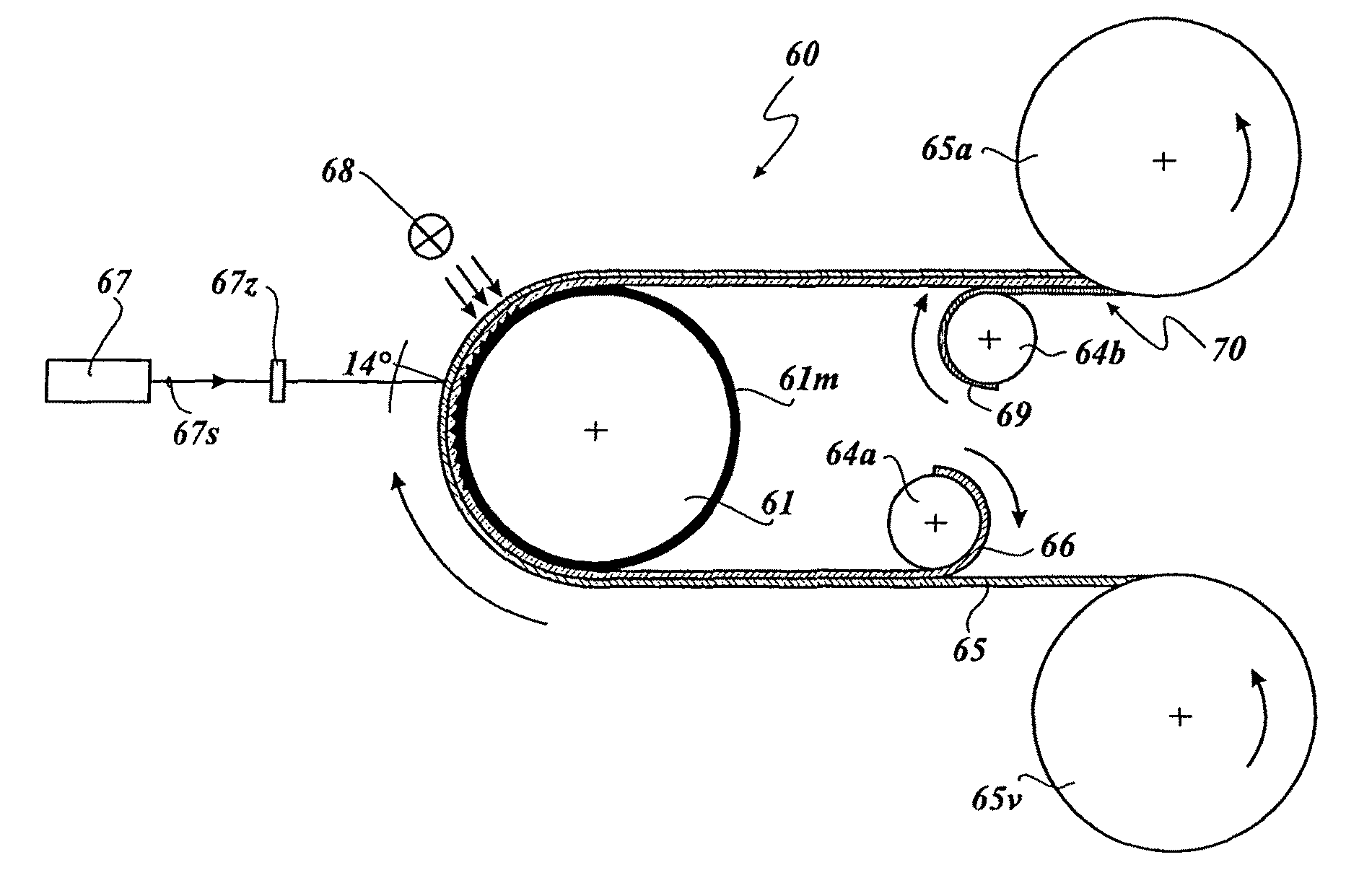
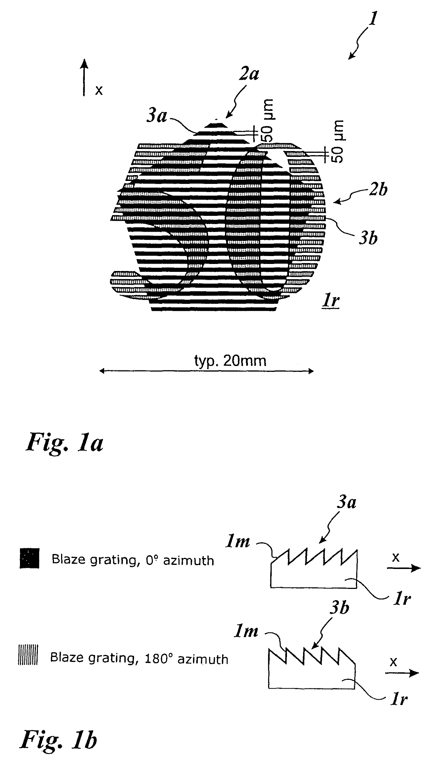
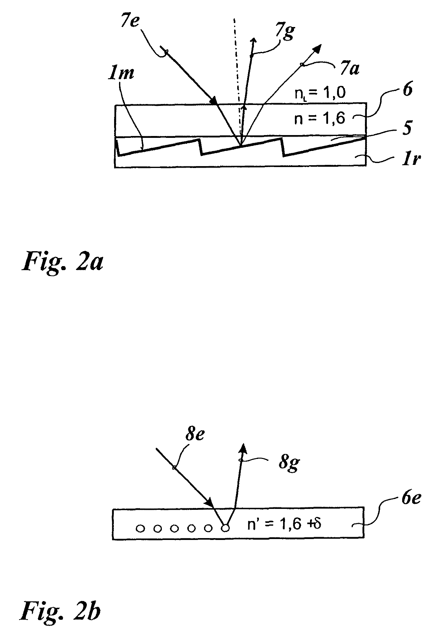
The invention provides a process for producing a volume hologram with two or more separate items of image information using a master with interlaced regions of different surface structures containing the different items of information. The process involves exposing a photosensitive layer with the master and a coherent light beam, resulting in the volume hologram being fixed by hardening the photosensitive layer. The invention also provides a master for producing the volume hologram and a transparent layer with the non-homogeneous refractive index. The volume hologram can be produced using an optical contact copy of the master. The invention also provides a security element with the volume hologram and a method for producing it. The technical effects of the invention include the ability to produce a volume hologram with high-quality image information and the efficient use of materials and processes for mass production.

Problems solved by technology

For mass-produced items, surface holograms are frequently used, which on the one hand do not produce an optimum image impression and which on the other hand can be copied by copying the shape of the surface relief.
They cannot be copied by shaping of a surface relief.
A disadvantage in that respect however is on the one hand the increased thickness—volume holograms are of a thickness which is a multiple of the light wavelength used to produce them—and the high demands in terms of register accuracy of the volume hologram layers.
Such volume holograms are admittedly more forgery-proof than the master hologram, but they are optically no higher in quality than a surface hologram.

Method used


Image

  • Multi-layer body with volume hologram
  • Multi-layer body with volume hologram
  • Multi-layer body with volume hologram

Examples


first embodiment

[0083]FIGS. 3a to 3i now show the process steps for the production of the multi-layer body according to the invention.

[0084]FIG. 3a is a diagrammatic view in section showing a replication layer 34 which can be formed from a thermoplastic material, in the top side of which are provided regions in which asymmetrical relief structures 30a and 30b in the form of blaze gratings are formed, the relief structures involving an arrangement turned through 180°, of the same configuration. The relief structures 30a and 30b in the embodiment shown in FIGS. 3a to 3i have a grating width of 10 μm, that is to say a spatial frequency of 100 lines / mm, and a grating depth of 2 mm, with the total thickness of the replication layer 34 being 22 μm. The top side of the replication layer 34 further has regions with a relief structure 30h forming a background region for the regions with the relief structures 30a and 30b. The relief structure 30h has a markedly higher depth-to-width ratio than the relief str...

second embodiment

[0092]FIGS. 4a to 4h now show the process steps for the production of the multi-layer body according to the invention.

[0093]FIG. 4a shows a diagrammatic view in section illustrating a replication layer 44 which can be formed from a thermoplastic material and in the top side of which are provided regions in which are shaped asymmetrical relief structures 40a and 40b which are in the form of blaze gratings and which, being of the same configuration, are in an arrangement of being turned through 180°. The relief structures 40a and 40b, in the embodiment shown in FIGS. 4a to 4h, involve the same parameters as in the embodiment illustrated hereinbefore in FIGS. 3a to 3i (10 μm grating width, 2 μm grating depth, 22 μm total thickness for the replication layer 44).

[0094]FIG. 4b now shows the replication layer 44 with a metallic layer 44m applied to the top side of the replication layer. The metallic layer 44m can be applied for example by sputtering. The metallic layer 44m can involve meta...

third embodiment

[0100]FIGS. 5a to 5g now show the process steps for the production of the multi-layer body according to the invention.

[0101]FIG. 5a shows a replication layer 54 of PET with regions having relief structures 50a and 50b which, as in the above-described embodiments, differ from each other substantially by their arrangement of being turned through 180° and which involve blaze gratings. The relief structures 50a and 50b however can also be of different configurations and can differ from each other for example in grating spacing and / or grating depth and / or the angle of inclination of the grating flanks. In the FIG. 5a embodiment the grating spacing of the relief structures 50a and 50b is 10 μm, the grating depth is 2 μm and the overall thickness of the replication layer 54 is less than 12 μm.

[0102]Applied to the top side of the replication layer 54, that has the relief structures 50a and 50b, is a metallic layer 54m which can be like the metallic layers in the above-described embodiments ...


PUM


Abstract

Described is a process for the production of a multi-layer body having a volume hologram with at least two different items of image information, wherein a photosensitive layer (46) of the multi-layer body is directly or with the interposition of a transparent optical medium (44s, 45) brought into contact with the front side of a master (44), in which interlaced regions with different asymmetrical surface structures or kinoform structures are shaped, which embody the at least two different items of image information. The photosensitive layer (46) and the master are exposed with a coherent light beam (47) whereby a volume hologram is formed in the photosensitive layer (46). Also described are a master for the production of the multi-layer body and a security element having said multi-layer body.

Description

[0001]This application claims priority based on an International Application filed under the Patent Cooperation Treaty, PCT / EP2007 / 003091, filed on Apr. 5, 2007 and German Application No. DE 102006016139.4-51, filed on Apr. 6, 2006.BACKGROUND OF THE INVENTION[0002]The invention concerns a process for the production of a multi-layer body having a volume hologram, a master for the production of the volume hologram and a security element having the multi-layer body.[0003]Holograms are used as security elements for protecting security documents such as banknotes, identity cards or passports, security cards or the like to achieve a high level of forgery-proofness. For mass-produced items, surface holograms are frequently used, which on the one hand do not produce an optimum image impression and which on the other hand can be copied by copying the shape of the surface relief.[0004]Volume holograms, also referred to as white light holograms or reflection holograms, are based on light diffr...

Claims


Application Information

Patent Timeline
Patent Type & Authority Patents(United States)
IPC IPC(8): G03H1/02
CPCG03H1/0011G03H1/202B42D25/328G03H1/0248G03H1/26G03H2001/0027G03H2001/043G03H2001/186G03H2001/207G03H2001/2635G03H2001/0415
Inventor STAUB, RENETOMPKIN, WAYNE ROBERTSCHILLING, ANDREASBREHM, LUDWIGHANSEN, ACHIM
Owner OVD KINEGRAM AG
Learn More