Organic light emitting diode arrangement

a light-emitting diode and organic technology, applied in the direction of electric variable regulation, process and machine control, instruments, etc., can solve the problem that high value may damage the organic light-emitting diode arrangemen

Active Publication Date: 2012-05-29
KONINK PHILIPS ELECTRONICS NV
View PDF13 Cites 3 Cited by
  • Summary
  • Abstract
  • Description
  • Claims
  • Application Information

AI Technical Summary

Benefits of technology

[0003]It is an object of the invention, to provide an organic light emitting diode arrangement, that comprises a protection against an effect of a switch-on.
[0005]The circuit for, during the first time interval that follows the switch-on, limiting the current through the organic light emitting diode arrangement, forms a protection against an effect of a switch-on. Owing to the fact that an organic light emitting diode arrangement is a highly capacitive arrangement that represents a low impedance connection when being turned on, an inrush current that has a too high value may damage the organic light emitting diode arrangement. By limiting the inrush current, any damage from the inrush current may be prevented. The fact, that the circuit limits the current through the organic light emitting diode arrangement during the first interval more than during the second time interval that follows the first time interval, results in an acceptable efficiency of the protected organic light emitting diode arrangement, owing to the fact that the protection is mainly offered when necessary and is reduced when not necessary.
[0007]An embodiment of the organic light emitting diode arrangement is defined by the circuit comprising a passive circuit. Usually a passive circuit does not need to be controlled and is therefore relatively simple.
[0009]An embodiment of the organic light emitting diode arrangement is defined by the circuit comprising a series inductor. A series inductor has a relatively large impedance value when a current starts flowing through this inductor and has a relatively small impedance value when the current has been flowing through this inductor for a while and is only slowly changing. Compared to a negative temperature coefficient resistor, an inductor does not need to be resetted and does not dissipate any power in an ideal situation. For commutation purposes, a freewheel diode may be coupled serially to the series inductor and in parallel to a switchable DC source, to avoid large voltage spikes when turning the DC source off. In case of using a switchable AC source with a rectifier bridge, the rectifier bridge may take care of the commutation.
[0011]An embodiment of the organic light emitting diode arrangement is defined by the circuit comprising an active circuit. Usually an active circuit performs a switching function. Compared to a passive circuit, an active circuit may be more accurate.
[0016]A problem, to provide an organic light emitting diode arrangement, that comprises a protection against an effect of a switch-on, is solved. The organic light emitting diode arrangement is further advantageous, in that the protected organic light emitting diode arrangement has an acceptable efficiency.

Problems solved by technology

Owing to the fact that an organic light emitting diode arrangement is a highly capacitive arrangement that represents a low impedance connection when being turned on, an inrush current that has a too high value may damage the organic light emitting diode arrangement.
In other words, during the first time interval the current through the organic light emitting diode arrangement is limited according to a first limitation, and during the second time interval the current through the organic light emitting diode arrangement is limited according to a second limitation, the second limitation resulting in a smaller impact than the first limitation or resulting in no limitation at all and / or no impact at all.

Method used


Image

  • Organic light emitting diode arrangement
  • Organic light emitting diode arrangement
  • Organic light emitting diode arrangement

Examples


Embodiment Construction

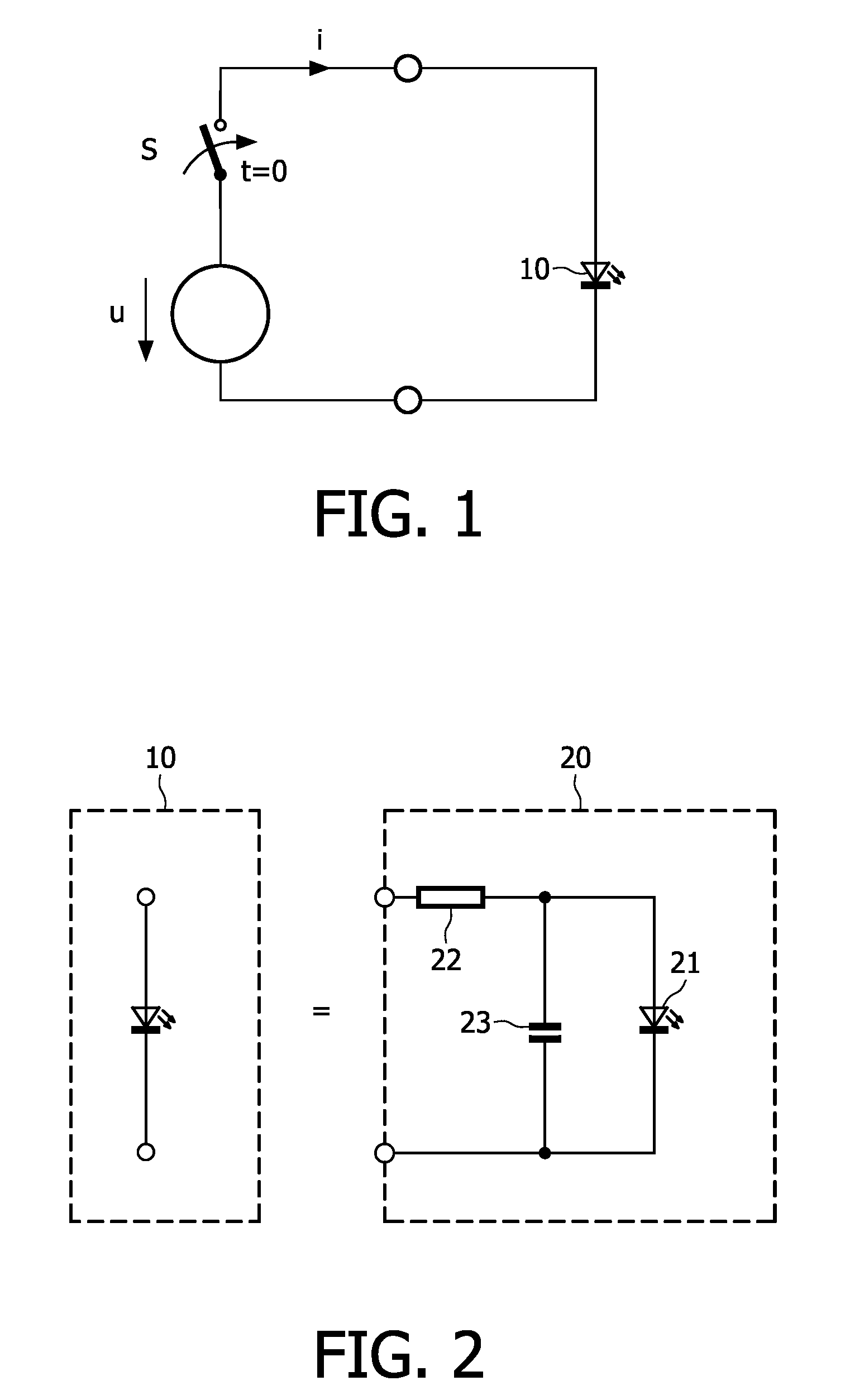
[0033]The organic light emitting diode 10 shown in the FIG. 1 is coupled to a source u,i for generating a voltage u and a current i via a switch S that is closed at a time t=0.

[0034]The equivalence 20 of an organic light emitting diode 10 shown in the FIG. 2 comprises a diode 21 coupled in parallel to a capacitor 23. The parallel diode 21 and capacitor 23 are coupled to a resistor 22 serially.

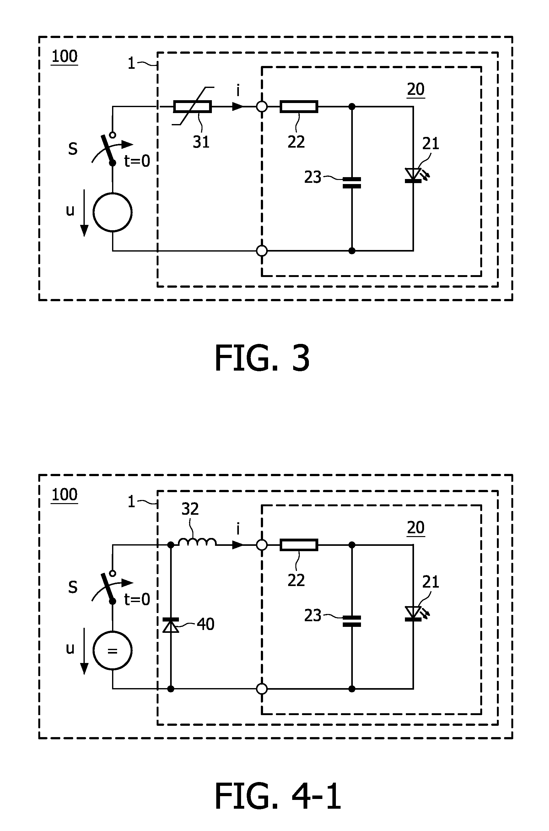
[0035]The device 100 according to the invention shown in the FIG. 3 comprises a first organic light emitting diode arrangement 1 according to the invention. This first organic light emitting diode arrangement 1 comprises the equivalence 20 coupled to the source u,i and switch S shown in the FIG. 1 via a negative temperature coefficient resistor 31.

[0036]The device 100 according to the invention shown in the FIG. 4 comprises a second organic light emitting diode arrangement 1 according to the invention. This second organic light emitting diode arrangement 1 comprises the equivalence 20 coupled t...


PUM


Abstract

Organic light emitting diode arrangement Organic light emitting diode arrangements (1) are, to protect them against an effect of a switch-on, provided with circuits (31-36) for, during a first time interval that follows a switch-on, limiting a current through the organic light emitting diode arrangement (1) more and for, during a second time interval that follows the first time interval, limiting the current less. The circuit (31-36) may be passive such as a negative temperature coefficient resistor (31) or a series inductor (32) possibly with a freewheel diode (40) or may be active such as a switchable resistor (33) that is not bridged during the first time interval and that is bridged during the second time interval or a switchable resistor that is bridged in response to a detection of a value of the current exceeding a threshold value or such as a part of a converter (63) that is controlled in response to a detection of a value of the current.

Description

FIELD OF THE INVENTION[0001]The invention relates to an organic light emitting diode arrangement, and also relates to a device comprising such an organic light emitting diode arrangement.BACKGROUND OF THE INVENTION[0002]Organic light emitting devices are highly capacitive arrangements representing a low impedance connection when being turned on. For example, WO2005015640 discloses an organic light emitting device to be driven at high voltages. However, when being turned on, high inrush currents may damage the organic light emitting device.SUMMARY OF THE INVENTION[0003]It is an object of the invention, to provide an organic light emitting diode arrangement, that comprises a protection against an effect of a switch-on.[0004]Thereto, the organic light emitting diode arrangement is defined by comprising a circuit for, during a first time interval that follows a switch-on, limiting a current through the organic light emitting diode arrangement more than during a second time interval that...

Claims


Application Information

Patent Timeline
Patent Type & Authority Patents(United States)
IPC IPC(8): H05B41/16H05B44/00
CPCH05B33/0896H05B45/60Y02B20/30H01L23/576H01L28/10H10K59/86
Inventor HENTE, DIRKJACOBS, JOSEPH HENDRIK ANNA MARIAVERJANS, CONRAD WILHELMUS ADRIAANWAFFENSCHMIDT, EBERHARD
Owner KONINK PHILIPS ELECTRONICS NV
Why Eureka
Try Eureka