Device for detecting the location of a compression point

a technology for detecting the location of compression points, applied in the direction of resistors, electrical/magnetic measuring arrangements, converting sensor output, etc., can solve the problem of impaired linearity of potentiometers, and achieve the effect of improving the elastic recovery behavior of devices and less temperature-dependen

Active Publication Date: 2012-05-29
HOFFMANN KRIPPNER
View PDF14 Cites 3 Cited by
  • Summary
  • Abstract
  • Description
  • Claims
  • Application Information

AI Technical Summary

Benefits of technology

[0006]It is an object of the invention to improve the elastic recovery behavior of a device of the type mentioned in the Background of the Invention and to make it less temperature-dependent.
[0008]The leaf spring functions as mechanical protection for the device. During actuation of this device when the substrates are pressed together, this leaf spring is deformed together with the device. The additional mounting of the leaf spring may therefore indeed increase the necessary actuating force. However, the switching threshold of the device can be set more precisely, and the size of the contact zone between resistive element and contact electrode is potentially increased and the switching behavior of the device is smoother. Furthermore, the leaf spring mounted flush on the substrate of film material acts very effectively as a restoring spring, which promptly eliminates the dimples formed during actuation of the device and also has no noteworthy temperature dependence. The linearity of the device is therefore stable with respect to temperature or is not notably impaired by temperature influences.
[0015]Conventional film potentiometers can be equipped with the leaf spring during manufacture or else retrofitted with the leaf spring. The leaf spring can be mounted directly on the film potentiometer, for example by adhesive bonding. It prevents dimples in the film material and it ensures a well-defined restoring force. Fatigue phenomena of the films due to temperature and continuous load are compensated, and scratches and damage due to external influences are greatly reduced.

Problems solved by technology

Because of the temperature dependence of the recovery behavior, the linearity of the potentiometer can be impaired.

Method used


Image

  • Device for detecting the location of a compression point
  • Device for detecting the location of a compression point
  • Device for detecting the location of a compression point

Examples


Embodiment Construction

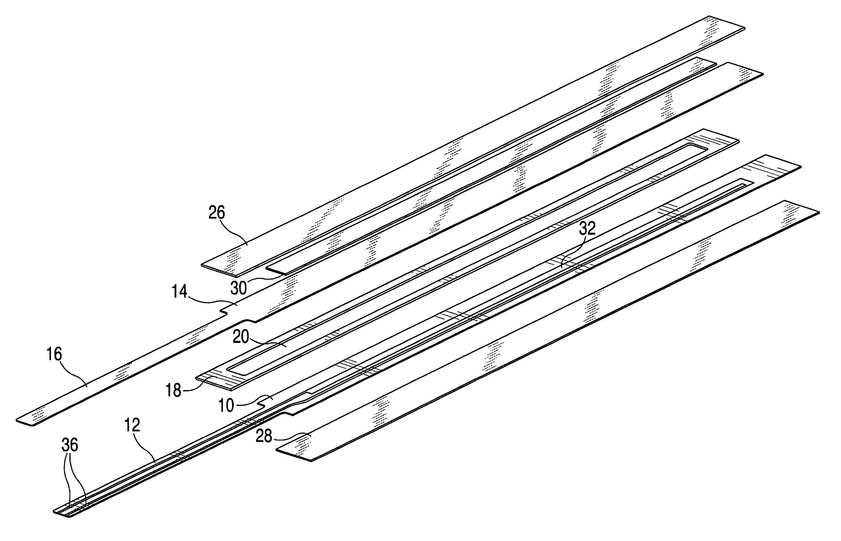
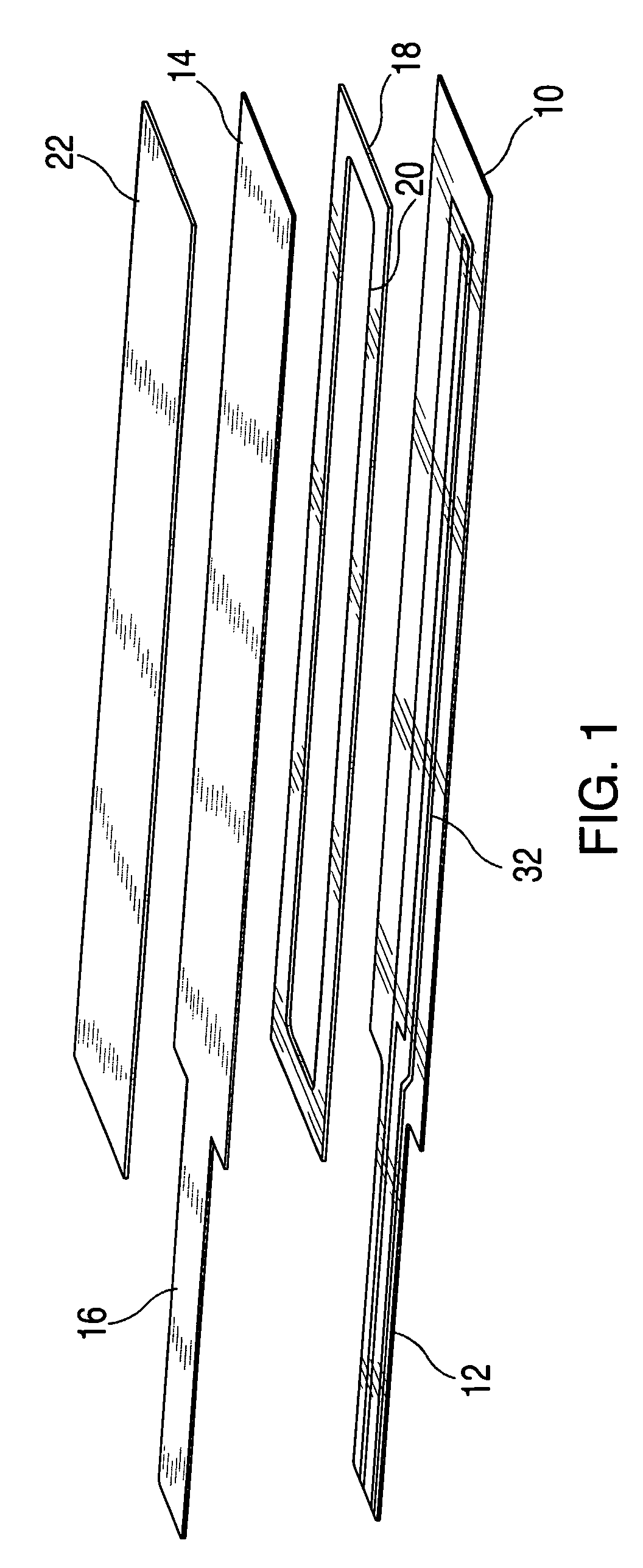
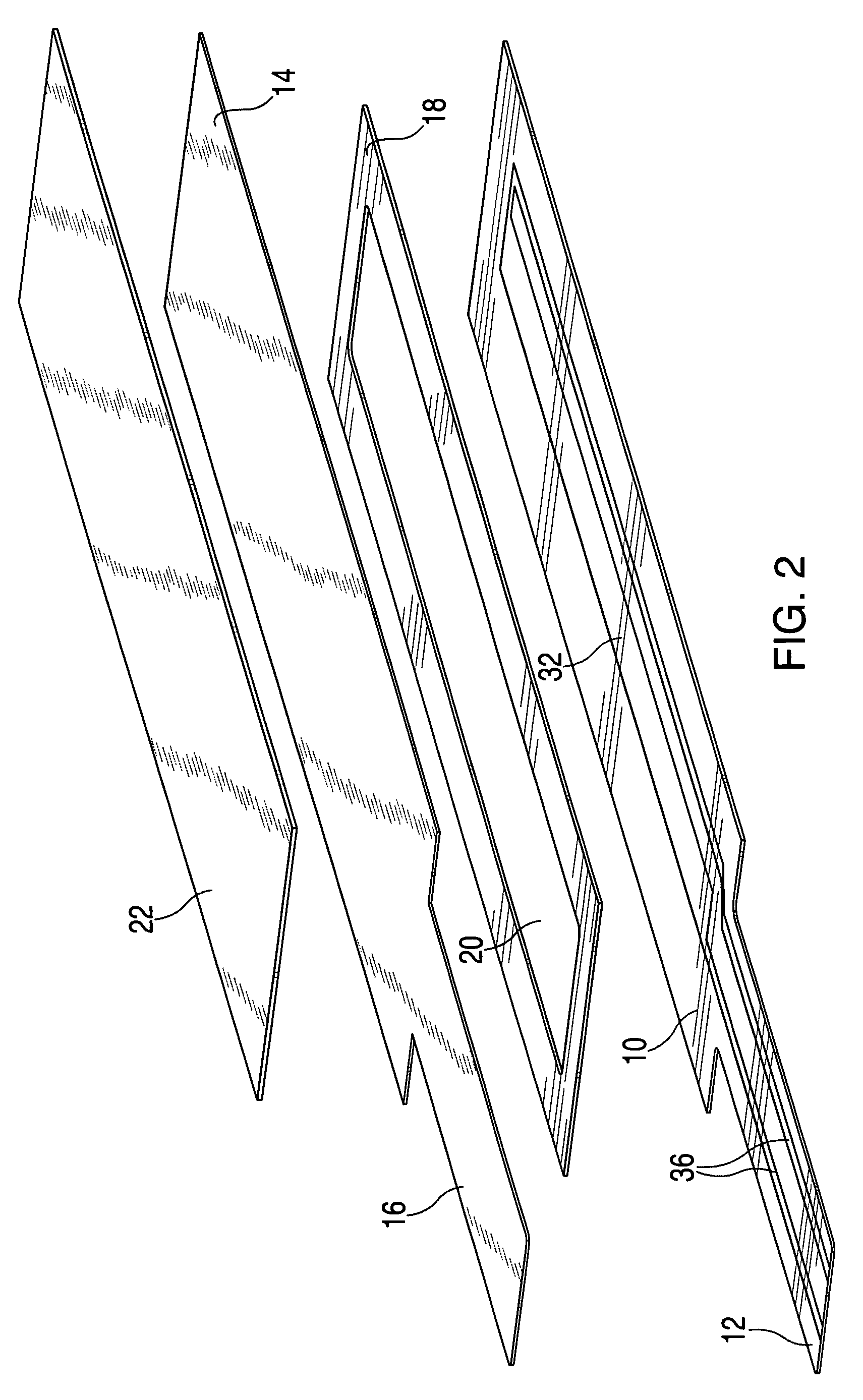
[0034]The film potentiometer according to FIG. 1 has a substrate 10 for a resistive element 32, which is made of film material. Substrate 10 has the shape of an elongated rectangle, and resistive element 32 is straight. At the one narrow end of substrate 10 there protrudes in the prolongation thereof a somewhat narrower contact tab 12, which supports two parallel conductor tracks 36 for establishing bipolar contact with resistive element 32 at both ends.

[0035]Disposed opposite substrate 10 of resistive element 32 is a second substrate 14 of the same shape and size for a contact electrode, which functions as the tapping electrode of the potentiometer. Second substrate 14 is also made of film material. The contact electrode is straight. It extends, following the path of the resistive element, over the center of resistive element 32, and for the same length. At the same narrow end as that of first substrate 10, second substrate 14 has a contact tab 16, which supports one conductor trac...


PUM


Abstract

The device has a first substrate on which an electrical resistive element is mounted, and a second substrate on which a contact electrode is mounted. The contact electrode is disposed opposite the resistive element at an electrically insulating distance. It can be brought into electrical contact with the resistive element by pressing the substrates together. The device is provided with electrical or electronic circuitry for detecting the location of the compression point. At least one of the substrates is equipped with a flat leaf spring of spring-grade sheet metal attached flush thereto, which leaf covers the compression zone of the substrates.

Description

FIELD OF THE INVENTION[0001]The invention relates to a device for detecting the location of a compression point, with a first substrate on which an electrical resistive element is mounted, with a second substrate on which a contact electrode is mounted, which electrode is disposed opposite the resistive element at an electrically insulating distance and can be brought into electrical contact with the resistive element by pressing the substrates together, and with an electrical or electronic circuit for detecting the location of the compression point.BACKGROUND OF THE INVENTION[0002]From DE 4335004 A1, DE 20013047 U1 and DE 10060013 A1 there are known what are called film potentiometers. In these potentiometers, the substrates of the resistive elements and of the contact electrodes are made of film material. Between the substrates there is mounted a spacer of film material, thereby creating the insulating distance between the resistive element and the contact electrode.[0003]To actua...

Claims


Application Information

Patent Timeline
Patent Type & Authority Patents(United States)
IPC IPC(8): H01C10/12
CPCG01B7/003G01D5/165H01C10/10
Inventor BERRES, STEFAN
Owner HOFFMANN KRIPPNER
Why Eureka
Try Eureka