Boat drive-supported wake generating device

a wake generation and drive-supported technology, applied in the direction of marine propulsion, special-purpose vessels, vessel construction, etc., can solve the problems of large interior or storage space, high strain on the hull to manage wakeplate and propulsive loads, and large internal or storage spa

Inactive Publication Date: 2012-06-05
BAYWOL ROGER J
View PDF7 Cites 36 Cited by
  • Summary
  • Abstract
  • Description
  • Claims
  • Application Information

AI Technical Summary

Benefits of technology

[0007]The device described herein is intended to provide for the sustained creation of large wakes, utilizing the forward and downward thrust of the drive unit of an outboard or sterndrive motor to provide a forward and downward force upon wake-augmentation plates. Larger wakes are created through the deflection of water downward aft of the boat, while at the same time the downward force conveyed upon the plates prevents the back of the boat from rising. The force between the drive unit and the plates is conveyed by means of a one- or multi-piece support bar. By using such a support bar, forces can be more directly transferred between the drive unit and wake-augmentation plates without significantly stressing the outboard or sterndrive mountings or trim mechanisms, or the boat hull.

Problems solved by technology

The use of water ballast in bladders or built-in tanks inside the boat is a common practice to increase the size of the wake of any given boat, thus giving it greater utility as a tow vehicle, but consumes significant interior or storage space, and adds large stresses within the boat structure due to the weight of the water.
U.S. Pat. No. 7,434,531 specifically addresses adjusting a boat's wake for water sports, but the hydraulic units used to force down the wake-adjustment plates into the water flow are mounted directly to the boats hull, creating high strains in the hull to manage wakeplate and propulsive loads, which limits the size of the plates.

Method used


Image

  • Boat drive-supported wake generating device
  • Boat drive-supported wake generating device
  • Boat drive-supported wake generating device

Examples


Embodiment Construction

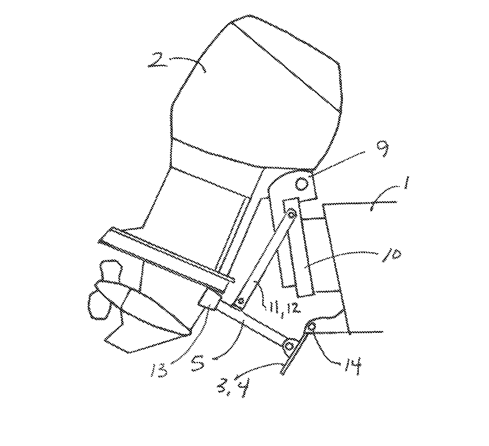
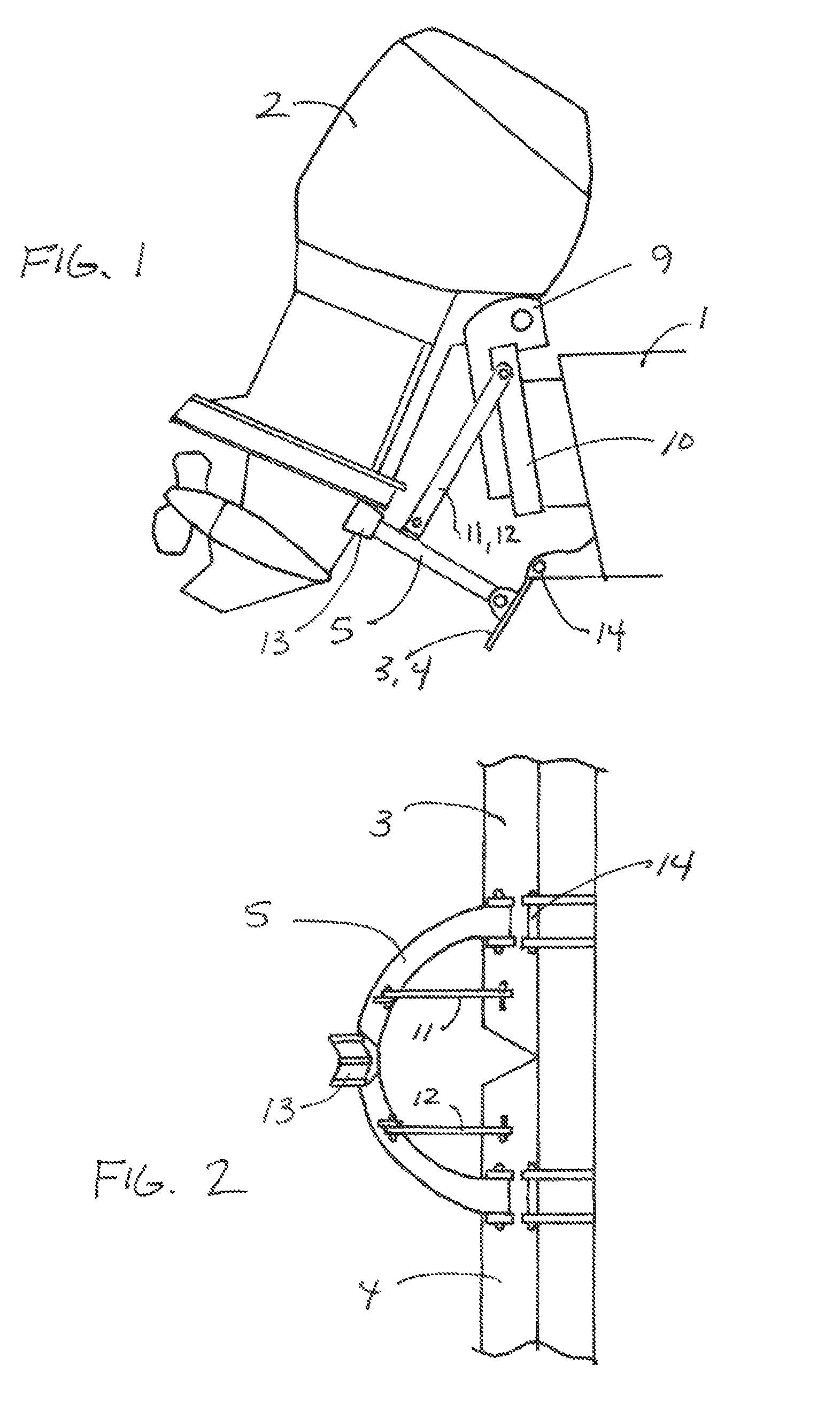
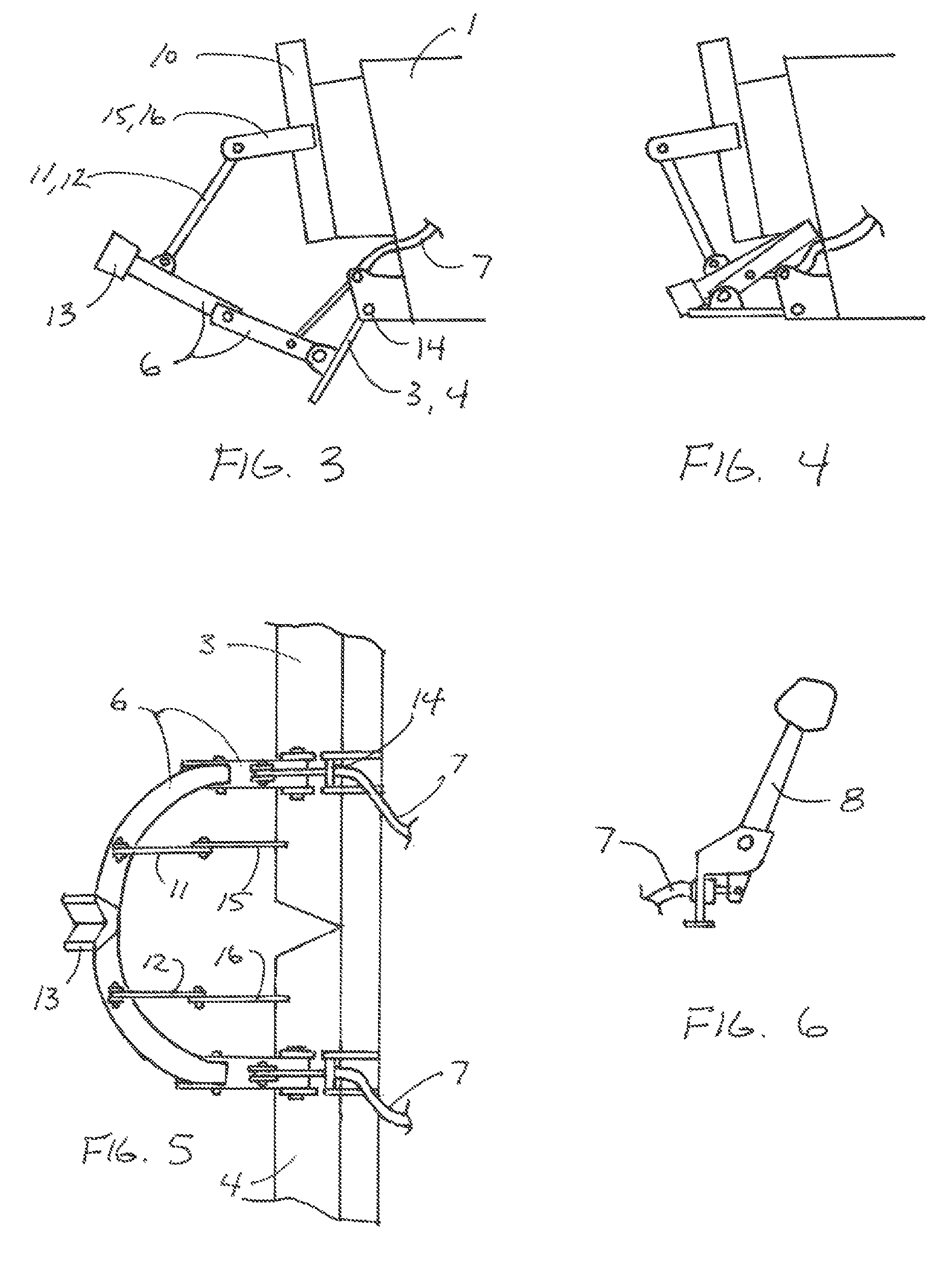
[0014]A boat hull (1) with outboard motor (2) or sterndrive unit has wake-augmentation plates (3&4) with spring-loaded pivots or hinges (14) mounted to the transom. Its motor or drive unit is raised, and a one-piece support bar (5) is installed, or a multi-piece articulating support bar assembly (6) is deployed by cables (7) as controlled from the driver's position or other position by a lever (8), or by a fluidic cylinder or electric actuator with appropriate control. Control linkages (11&12), with or without control linkage brackets (15&16), properly the position the support bar relative to the motor drive unit, with our without yoke (13). Once so configured, and the outboard motor or sterndrive unit is lowered by its integral trim unit (9), the support bar (5 or 6) transmits force from the outboard (2) or sterndrive unit to the wake-augmentation plates (3&4), rotating the plates below the bottom of the hull. As the boat's speed increases, additional propulsive force is transmitte...


PUM


Abstract

An apparatus which selectively increases the size of the wake of a boat with an outboard or sterndrive motor system. The apparatus has one or more plates attached to the boat hull which, when rotated below the bottom of the hull, extend into the flow of water when underway, increasing the size of the wake due to the dynamic displacement of water. A support bar mechanism transmits propulsive force from the motor drive unit to the plates to overcome resistive hydraulic loads. Linkages may be used to locate the support bar mechanism. In one embodiment, the support bar mechanism is comprised of a plurality of members and pivots such that the support bar mechanism can be stowed substantially out of the flow of water until larger wakes are desired. In other embodiments, mechanical cable, fluidic, or electrical control systems are used to control the configuration of the support bar mechanism.

Description

REFERENCE TO PRIOR APPLICATION[0001]The invention described herein was granted provisional patent 61 / 211,535 on Apr. 1, 2009.STATEMENT REGARDING FEDERALLY SPONSORED RESEARCH OR DEVELOPMENT[0002]Not Applicable.REFERENCE TO SEQUENCE LISTING, TABLE, OR COMPUTER PROGRAM LISTING COMPACT DISC APPENDIX[0003]Not Applicable.BACKGROUND OF THE INVENTION & DIFFERENCES TO THE PRIOR ART[0004]The use of a boat as a tow vehicle for various water sport activities includes the consideration of a wide range of desired wake characteristics for those sports. At one extreme, a minimal wake is desired for optimal barefoot and slalom skiing, where the wake is generally considered a nuisance. At the other extreme, as large a wake as possible is desired for wakeboarding and wakeskating, where the wake is considered a launch ramp for aerial tricks, and for wakesurfing where the wake face provides the means of conveyance for the rider. Generally, lighter boats with minimal “V” (deadrise) hulls have been used w...

Claims


Application Information

Patent Timeline
Patent Type & Authority Patents(United States)
IPC IPC(8): B63B1/22
CPCB63H20/08
Inventor BAYWOL, ROGER J
Owner BAYWOL ROGER J
Why Eureka
Try Eureka