Autosampler for high-performance liquid chromatography

a liquid chromatography and autosampler technology, applied in the direction of measuring devices, instruments, scientific instruments, etc., can solve the problems of at least in part unsuitable selection and achieve the effect of ensuring the service life of high-pressure injection valves and facilitating the realization of structures

Active Publication Date: 2012-06-12
DIONEX SOFTRON
View PDF13 Cites 18 Cited by
  • Summary
  • Abstract
  • Description
  • Claims
  • Application Information

AI Technical Summary

Benefits of technology

[0046]The present invention provides an autosampler for HPLC in which the required switching of liquid streams between very high pressure differences is possible by means of a high-pressure injection valve, with a sufficient service life of the high-pres

Problems solved by technology

In the prior art, the high-pressure injection valves are damaged at least in part by an unsuitable selection of the switching

Method used


Image

  • Autosampler for high-performance liquid chromatography
  • Autosampler for high-performance liquid chromatography
  • Autosampler for high-performance liquid chromatography

Examples


first embodiment

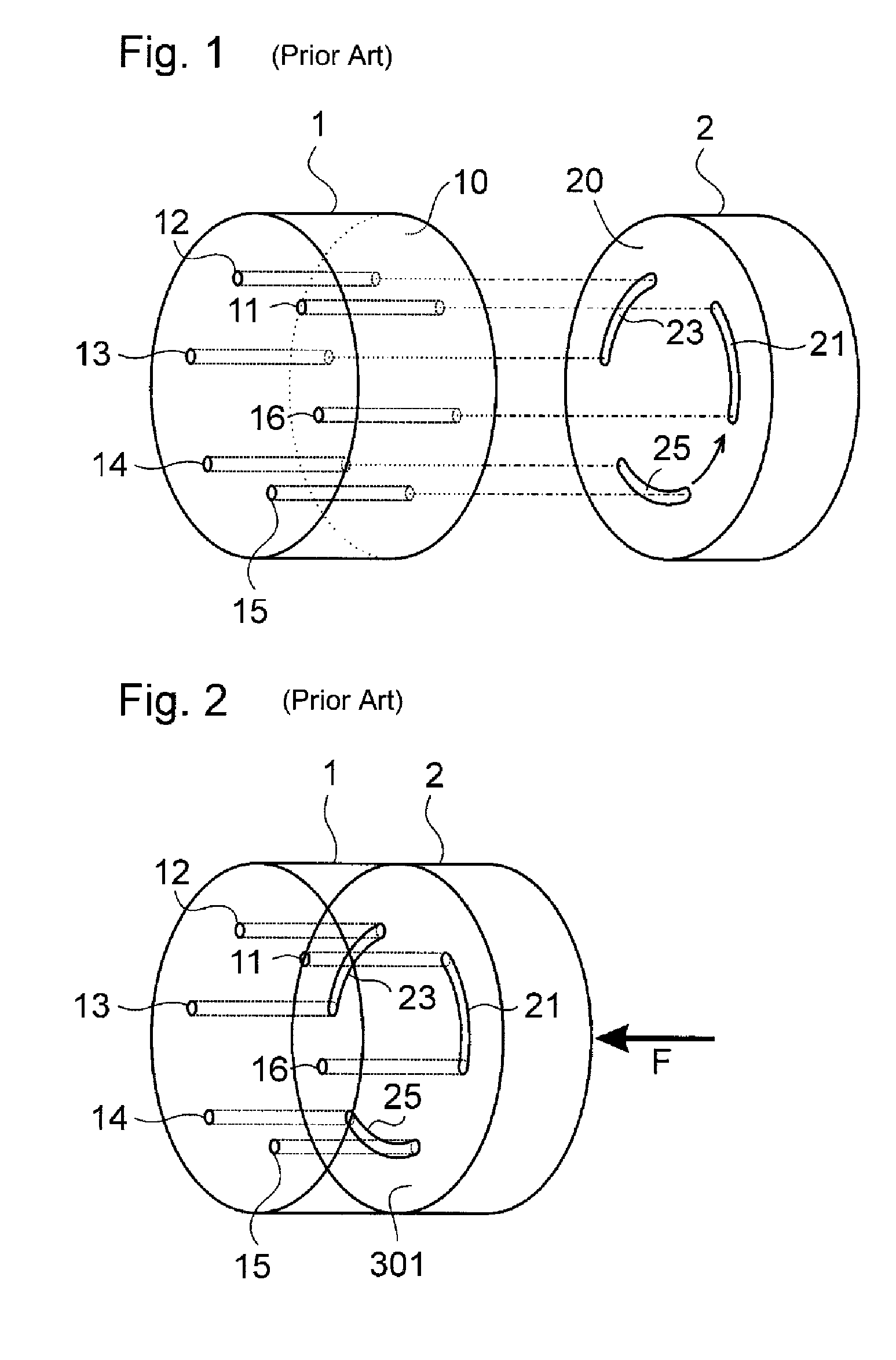
[0103]The reaching of the LOAD position again corresponds to FIG. 12. This consideration shows that with the valve according to the invention, and while maintaining the switching direction specified by the invention, all switching processes in which high pressure differences appear run such that the pressure from the respective port is reduced in the direction of the groove. In this way, the damage to the rotor and stator shown in FIGS. 6 and 7 is avoided. In the first embodiment described to this point, the invention has, in principle, already solved the problem completely.

[0104]The mode of operation of the invention is based, among other things, on an expedient temporal sequence of the individual sub-steps of the switching processes. Due to the above-described lengthening of the grooves, the temporal sequence of the switching processes is established in such a manner that the damaging situations are avoided. The prerequisite for the mode of operation is that a sufficient pressure ...

second embodiment

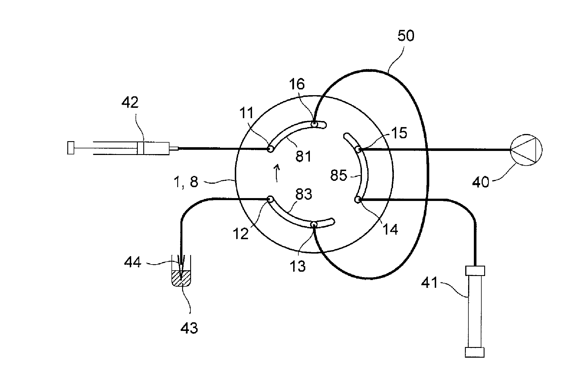
[0125]In the same representation as in FIG. 1, FIG. 22 shows an injection valve according to the invention with grooves 131, 151 machined into the modified stator 7. Rotor 2 is unchanged with respect to FIG. 1, with grooves 21, 23, 25. Groove 131 runs from port 13 in the direction of port 12 and has the effect that groove 23 is connected somewhat prematurely to port 13 when the valve is switched from the INJECT position into the LOAD position. Therefore the effect is exactly the same as shown in FIG. 16. Groove 151 runs from 11 port 15 in both directions. Groove 25 is thereby connected somewhat prematurely to port 15 in the switch from LOAD to INJECT, on the other hand, from INJECT to LOAD; groove 21 is connected prematurely to port 15.

[0126]FIG. 23 shows the second embodiment of the invention in the same representation and the same switching position as FIG. 16. Grooves 131, 151 in the stator are shown hatched for better distinction. One recognizes that, just as in FIG. 16, groove ...


PUM


Abstract

An autosampler for high-performance liquid chromatography (HPLC) with a high-pressure injection valve (1, 2) having improved life, particularly in high pressure operation. The geometry of the valve components and the connections of the high-pressure injection valve are provided such that the switching processes do not take place in a deleterious direction. The grooves in rotor (2) and/or the port opening cross sections (131, 151) in stator (1) and the rotational direction are selected such that fluid flows from grooves under high pressure in the direction of narrow, substantially pressure-free ports are avoided. This applies in particular to the switching process from INJECT to LOAD, since the sample loop contains a relatively large dead volume of compressed fluid. In addition, the valve can be controlled according to the invention in such a manner that an appropriate time is available for reducing harmful or undesired pressure differences.

Description

FIELD OF THE INVENTION[0001]The invention relates to an autosampler for high-performance liquid chromatography (HPLC), in particular an autosampler of the type used for injecting samples in HPLC.BACKGROUND[0002]A sample to be examined in HPLC must be fed into a high-pressure liquid stream, the latter being interrupted for as short a time as possible. High-pressure injection valves that allow a nearly interruption-free switching of the liquid stream are used for this purpose. Such a structure is described in U.S. Pat. No. 3,530,721, for example; the original application for the latter originates from the year 1965.[0003]The refinement of such an injection valve is mentioned, for instance, in U.S. Pat. No. 4,242,909. The basic principle of the valve shown there has largely established itself since then in HPLC. Since the present invention is based on this type of valve, the principle will be described in detail below.[0004]FIG. 1 shows such a high-pressure valve according to prior art...

Claims


Application Information

Patent Timeline
IPC IPC(8): G01N30/84
CPCG01N30/20G01N30/22G01N35/1097G01N2030/201G01N2030/202
Inventor HOCHGRAEBER, HERMANNRUEGENBERG, GERVIN
Owner DIONEX SOFTRON
Why Eureka
Try Eureka