Method for coating the quartz burner of an HID lamp

a technology of quartz burner and hid lamp, which is applied in the direction of coating, chemical vapor deposition coating, electric discharge lamp, etc., can solve the problems of large uv photon flux leaving the quartz burner unused, unable to achieve the desired effect, and inability to easily ensure the effect of success, etc., to achieve the effect of improving the energy balance, reducing the risk and ensuring the effect of uv photon flux

Inactive Publication Date: 2007-12-11
SCHOTT AG
View PDF21 Cites 0 Cited by
  • Summary
  • Abstract
  • Description
  • Claims
  • Application Information

AI Technical Summary

Benefits of technology

[0007]The object of the present invention is to create a method for coating a quartz burner of a HID lamp with a UV-reflecting layer system which is capable of being applied to the quartz burner with relatively simple means, which has a sufficient, adapted service life, and brings about a notable improvement in the energy balance.

Problems solved by technology

With the known HID lamps, however, large UV photon fluxes leave the quartz burner unused.
Due to the aggressive plasma medium in the quartz burner and the high operating temperatures of the burner, this cannot be easily ensured, however.
These known layer systems have not resulted in the desired success with quartz burners for HID lamps.

Method used


Image

  • Method for coating the quartz burner of an HID lamp
  • Method for coating the quartz burner of an HID lamp

Examples


Embodiment Construction

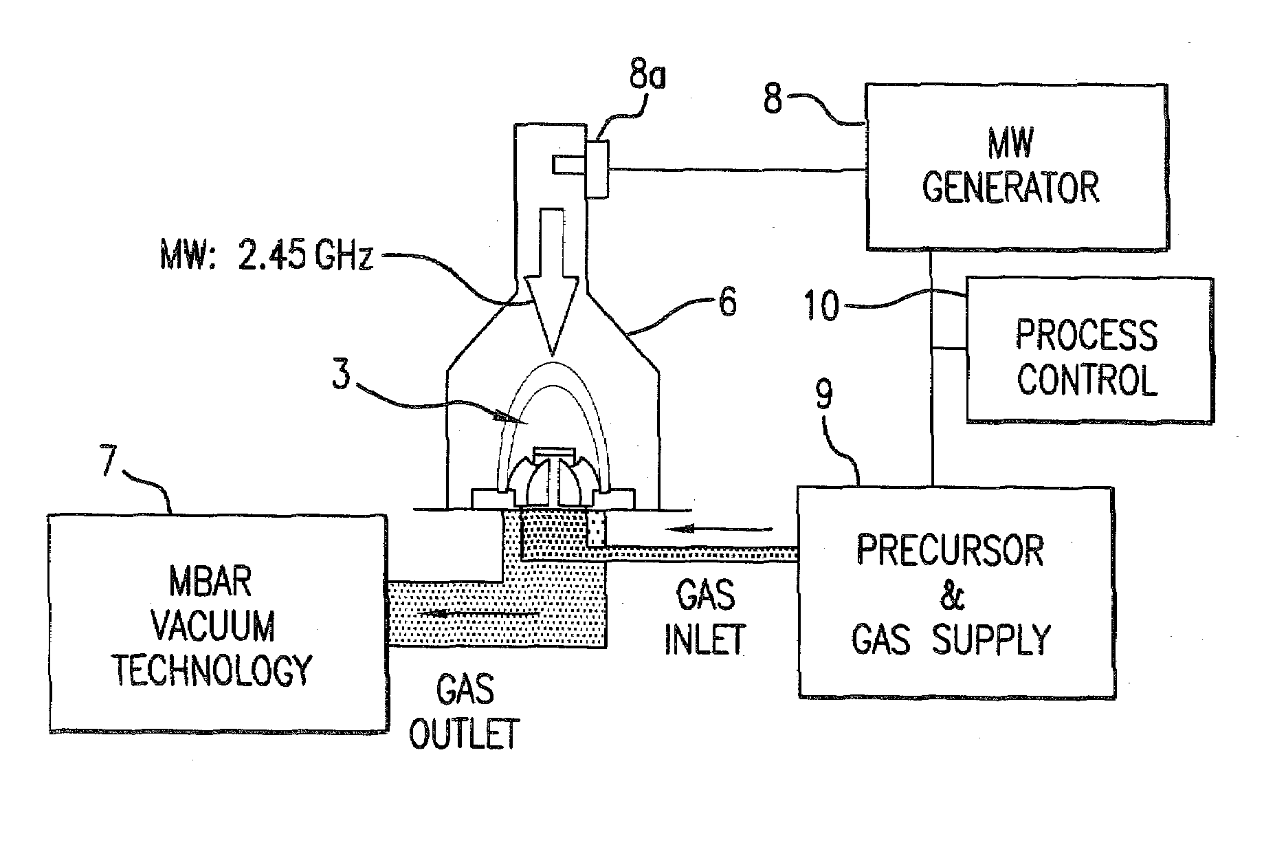
[0042]HID lamp 1 depicted in FIG. 1 is composed of a tubular jacket 2 and a quartz burner 3 with electrodes 4. “HID” is a technical term that stands for High Intensity Discharge.

[0043]The specific design and function of an HID lamp 1 of this type is known and therefore need not be explained further. As shown in the associated enlargement of a section, a UV-reflecting layer packet 5 is applied to the inner surface of burner wall 3a, the layer packet being composed of a large number, e.g., 50, of individual alternating layers made of Ti / Si oxide. Unshaded layers 5a represent Ti oxide layers, and shaded areas 5b represent Si oxide layers. The thickness of the individual layers typically ranges between 5 nm and 100 nm, whereby the thicknesses need not necessarily be distributed strictly equally; instead, accumulations of small layer thicknesses can also occur. This depends on the design. The layer thickness is preferably <1200 nm, however, because the layer then has high flexibility, an...


PUM

PropertyMeasurementUnit
thicknessaaaaaaaaaa
temperaturesaaaaaaaaaa
thicknessaaaaaaaaaa

Abstract

In order to improve the energy balance of an HID lamp, the quartz burner, preferably the inside thereof, is coated with a UV reflecting layer system by alternatingly applying amorphous thin layers made at least of titanium oxide and silicon oxide having the respective general stoichiometry TiOy and SiOx by means of a plasma impulse chemical vapor deposition (PICVD) method at a high power density and increased substrate temperatures ranging from 100° to 400° C., using small growth rates ranging from 1 nm/sec to 100 nm/sec so as to form an interference layer system having a thickness of less than 1200 nm and a minimized UV-active defective spot rate ranging from 0.1 to 1 percent.

Description

CROSS-REFERENCE[0001]The invention described and claimed hereinbelow is also described in POT / EP 03100827, filed on Jan. 28, 2003 and DE 102 04 363.9, filed Feb. 2, 2002. This German Patent Application, whose subject matter is incorporated here by reference, provides the basis for a claim of priority of invention under 35 U.S.C. 119(a)-(d).BACKGROUND OF THE INVENTION[0002]The present invention relates to a method for coating a quartz burner of a HID lamp with a UV-reflecting layer system.[0003]For illumination purposes with high illuminance, high-intensity or high intensity-discharge (HID) lamps are used which have a plasma quartz burner as the lamp, the lamp being located inside a tubular jacket.[0004]UV photons, which excite the atoms in the plasma to generate light in the visible range, play a central role in generating light in the plasma in the burner of HID lamps. With the known HID lamps, however, large UV photon fluxes leave the quartz burner unused. As such, the energy effi...

Claims


Application Information

Patent Timeline
Patent Type & Authority Patents(United States)
IPC IPC(8): H05H1/24H01J61/40C03C17/34C23C16/30H01J61/35
CPCH01J61/35C03C17/3417
Inventor MOEHL, WOLFGANGBEWIG, LARSKUEPPER, THOMASMARING, WOLFRAMMOELLE, CHRISTOPHER
Owner SCHOTT AG
Why Eureka
Try Eureka