
Bag valve

Inactive Publication Date: 2012-06-12
ECOPACK FRANCE
View PDF20 Cites 17 Cited by
  • Summary
  • Abstract
  • Description
  • Claims
  • Application Information

AI Technical Summary

Benefits of technology

[0014]The invention aims to remedy one or several of the abovementioned disadvantages and to provide a bag-on valve which allows for a guaranteed filling of a distributor containing such a valve, while reducing the risk of the bag being twisted and being torn during the filling phase of the recipient or in case of an accidental drop of the filled distributor.
[0015]This aim 1s reached according to the invention with an improved bag-on valve which comprises a flexible bag made of impermeable material and which is provided with an opening sealed by a valve which makes it possible to fill the bag with a desired product, whereby the empty bag is rolled up or folded round a longitudinal axis and is maintained in the rolled-up position, characterised in that the bag is provided with means making it possible to elongate the bag while it is being filled with the desired product.
[0016]In this way is obtained a bag which, as soon as it is filled, rests on the bottom of the recipient, which reduces the risk of the bag being torn in case of a fall.

Problems solved by technology

Only, while filling it with the product, the length of the bag-on valve becomes shorter as the bag is being filled, since the bag swells and expands laterally, which is disadvantageous in that the filled bag does not rest on the bottom of the recipient and, as a result, the bag containing the weight of the product is completely suspended on the valve, which implies that the bag will easily tear if the distributor is dropped by accident.
When the bag is unrolled while being filled with the product, there will be another problem in that the bag often has two upper corners which extend laterally and which hinder the unrolling movement as these corners come into contact with the inner wall of the recipient, resulting in the bag being twisted round the valve.
On the one hand, this twisting of the bag makes the bag weak, such that the bag may tear due to the effect of the mere twist, or due to the fact that, because of the twist, the filling volume is not sufficient to contain the quantity of product that is injected in case of an automatic filling.
On the other hand, the weakening caused by the twist makes the bag tear quicker when the distributor falls on the ground.
A disadvantage connected to the use of the label for maintaining the bag-on valve in the rolled-up position is that this label hinders the unfolding of the bag, thus causing a twist during the filling phase, which results in a weakening as described above.

Method used


Image

  • Bag valve
  • Bag valve
  • Bag valve

Examples


Embodiment Construction

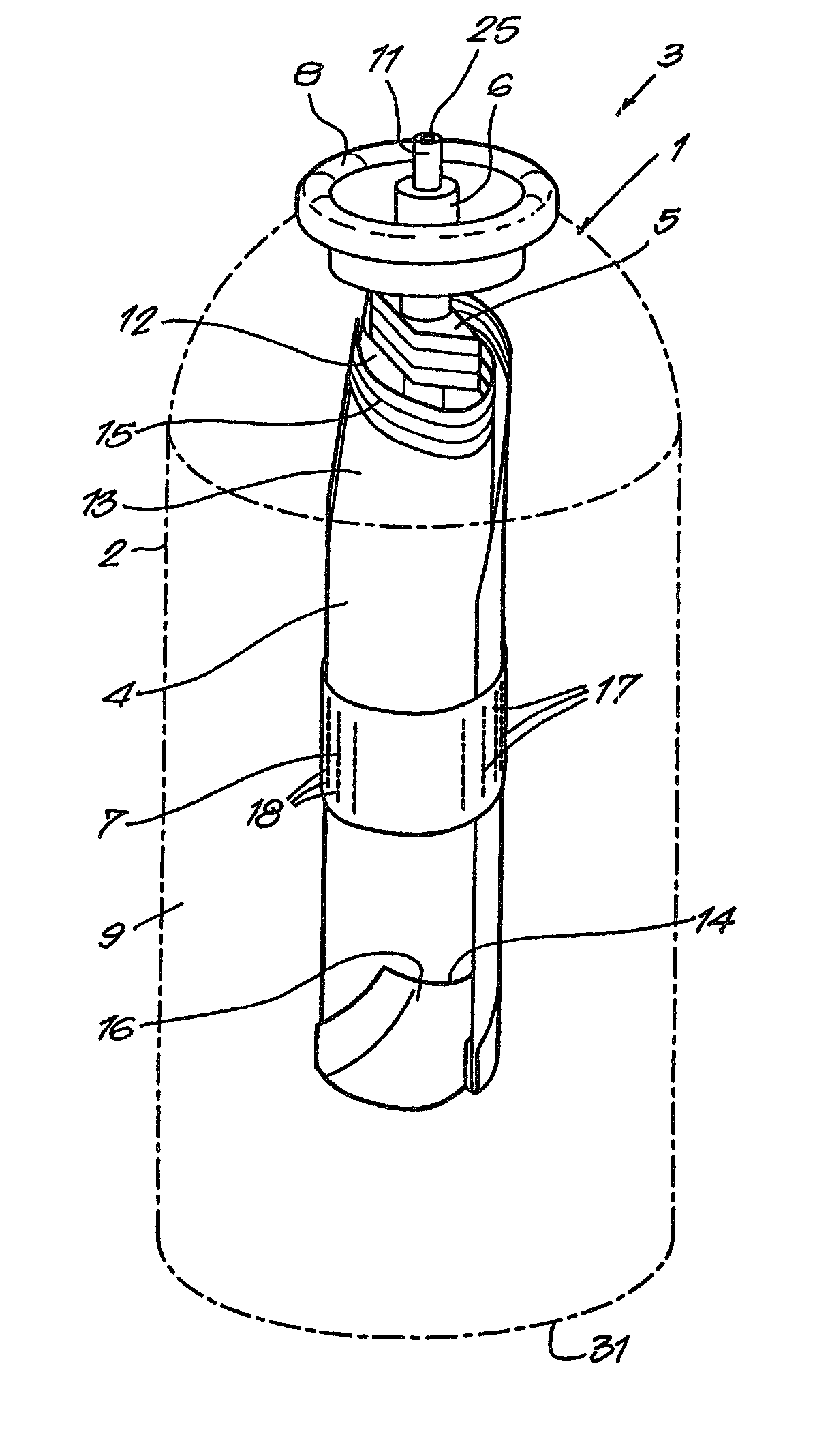
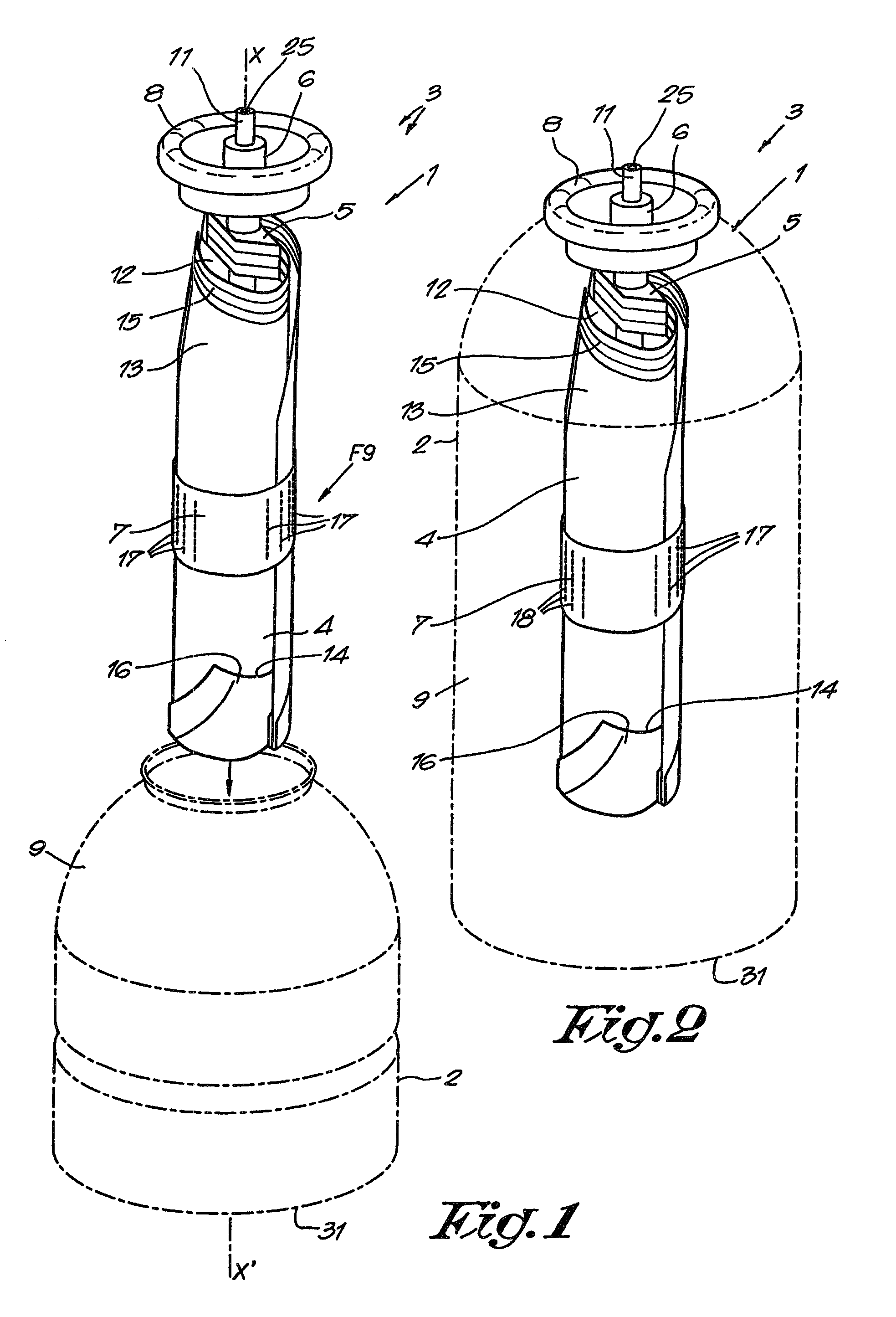
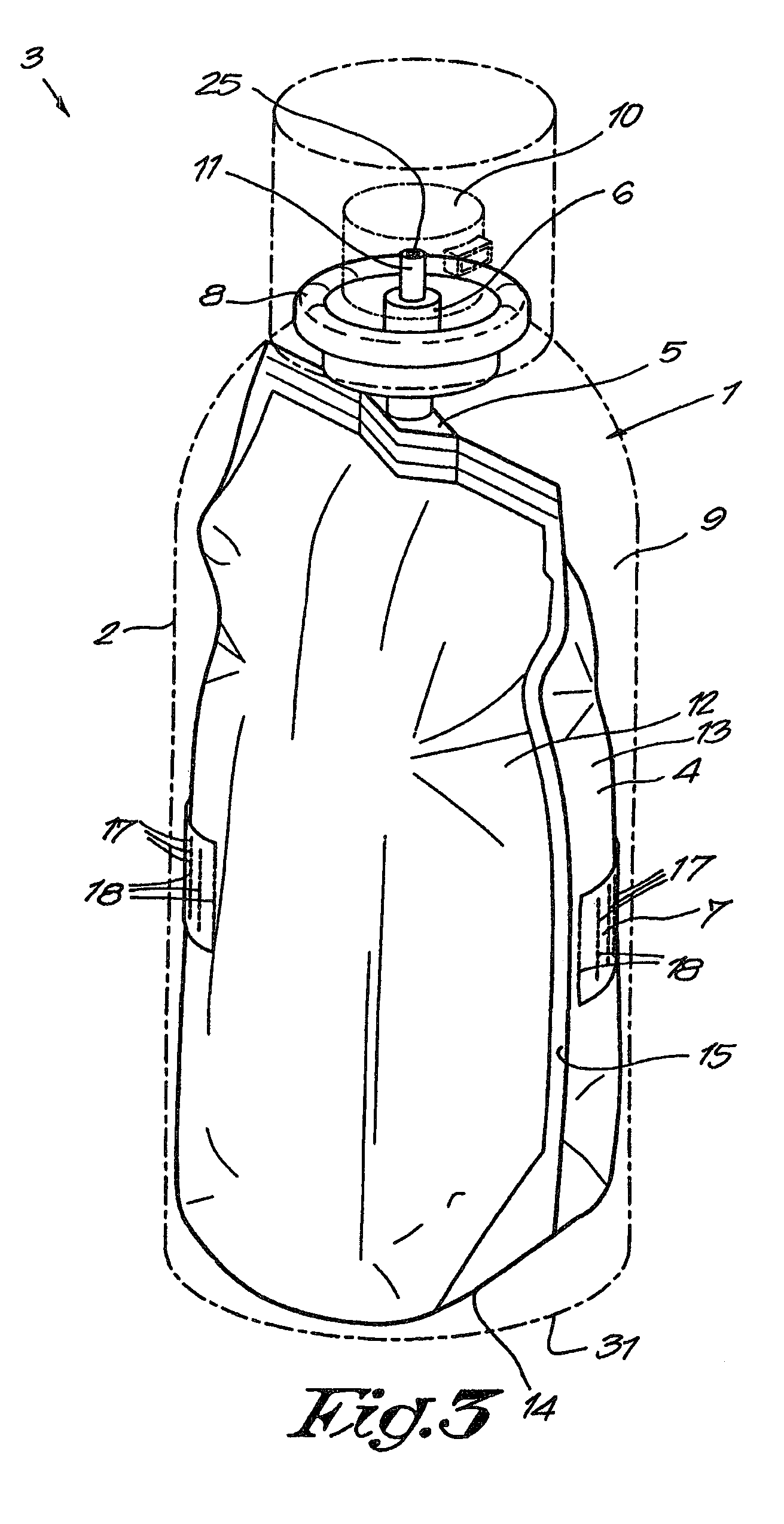
[0043]FIGS. 1 and 2 represent an improved bag-on valve 1 according to the invention, designed to be mounted in a recipient 2 of a product distributor as represented in FIG. 2.

[0044]The improved bag-on valve 1 comprises a flexible bag 4 made of impermeable material which is provided with an opening which is sealed by the body 5 of a valve 6 which makes it possible to fill the bag 4 with a desired product, whereby the empty bag 4 is rolled up or folded round a longitudinal axis X-X′ and is maintained in the rolled-up position by a label 7 glued round the rolled-up bag 4.

[0045]In the given example, the valve is fixed to the recipient 2 by means of a mounting-cup 8 which serves as a plug for the recipient so as to create a closed compartment 9 between the recipient 2 and the bag 4 which may contain a propellant gas.

[0046]After the assembly of the bag-on valve 1 and the recipient 2, the bag 4 is filled under pressure with any desired product, whereas the compartment 9 is filled with a qu...


PUM

PropertyMeasurementUnit
Lengthaaaaaaaaaa
Flexibilityaaaaaaaaaa
Shapeaaaaaaaaaa

Abstract

The improved bag valve includes a flexible bag (4) made of an impermeable material with an opening that is closed by a valve (6) for filling the bag (4) with a desired product. The empty bag (4) is rolled up or folded about a longitudinal axis (X-X′) and kept in the rolled position. The bag (4) is designed so as to elongate itself when filled with the desired product.

Description

BACKGROUND ART[0001]The invention concerns an improved bag-on valve.[0002]A bag-on valve is used in a distributor for a product under pressure such as for example an aerosol can.[0003]A bag-on valve generally comprises a flexible bag made of impermeable material which is made for example of two synthetic layers placed on top of one another and welded together at their girth, whereby an opening is left which is closed by a valve making it possible to fill the bag with the desired product.[0004]Such a bag-on valve is often rolled up or folded up, somewhat like a cigar, and it is maintained in the rolled-up position by a label glued round the rolled-up bag-on valve.[0005]This rolled-up bag-on valve is then introduced in a recipient with an opening which is shut by the valve of the bag-on valve.[0006]The distributor which is thus obtained by assembling the bag-on valve in the recipient is then filled with the product to be distributed on the one hand, which is introduced under pressure ...

Claims


Application Information

Patent Timeline
IPC IPC(8): B65B3/04
CPCB65D83/62B65D83/48B65D83/14B65D83/16
Inventor FRANSEN, ALFONS JOZEF
Owner ECOPACK FRANCE
Learn More