Apparatus for supporting a rotating shaft

a technology for supporting an apparatus and a rotating shaft, which is applied in the direction of rotating equipment, sliding contact bearings, machines/engines, etc., can solve the problems of premature wear of the pad and the housing

Inactive Publication Date: 2012-06-12
SIEMENS AG
View PDF26 Cites 3 Cited by
  • Summary
  • Abstract
  • Description
  • Claims
  • Application Information

AI Technical Summary

Benefits of technology

[0009]According to the present invention there is provided an apparatus for supporting a rotating shaft comprising: a housing surrounding the shaft; interposed between the housing and the shaft a plurality of tilting pads which extend in contiguous manner circumferentially around the shaft, each tilting pad being able to rock in the rotation of the shaft; and interposed between each pair of adjacent tilting pads retaining means for preventing circumferential movement of the pads around the housing due to rotation of the shaft, wherein the physical relationship between at least one tilting pad and its adjacent retaining means is such that said rocking of the pad takes place without circumferential slippage of the pad around the housing.
[0010]Preferably, the shaft rotates in a first sense so as to urge said at least one tilting pad against one of its adjacent retaining means, and the physical relationship between the pad and this one retaining means is such that throughout said rocking of the pad the end of the pad in contact with the retaining means remains in contact thereby to prevent circumferential movement of the pad around the housing in said first sense due to rotation of the shaft.

Problems solved by technology

The slippage back and forth of pad 14 circumferentially around housing 12 causes friction between the abutting faces of pad 14 and housing 12 with the result that there is premature wearing of the pad and housing.

Method used


Image

  • Apparatus for supporting a rotating shaft
  • Apparatus for supporting a rotating shaft
  • Apparatus for supporting a rotating shaft

Examples


Embodiment Construction

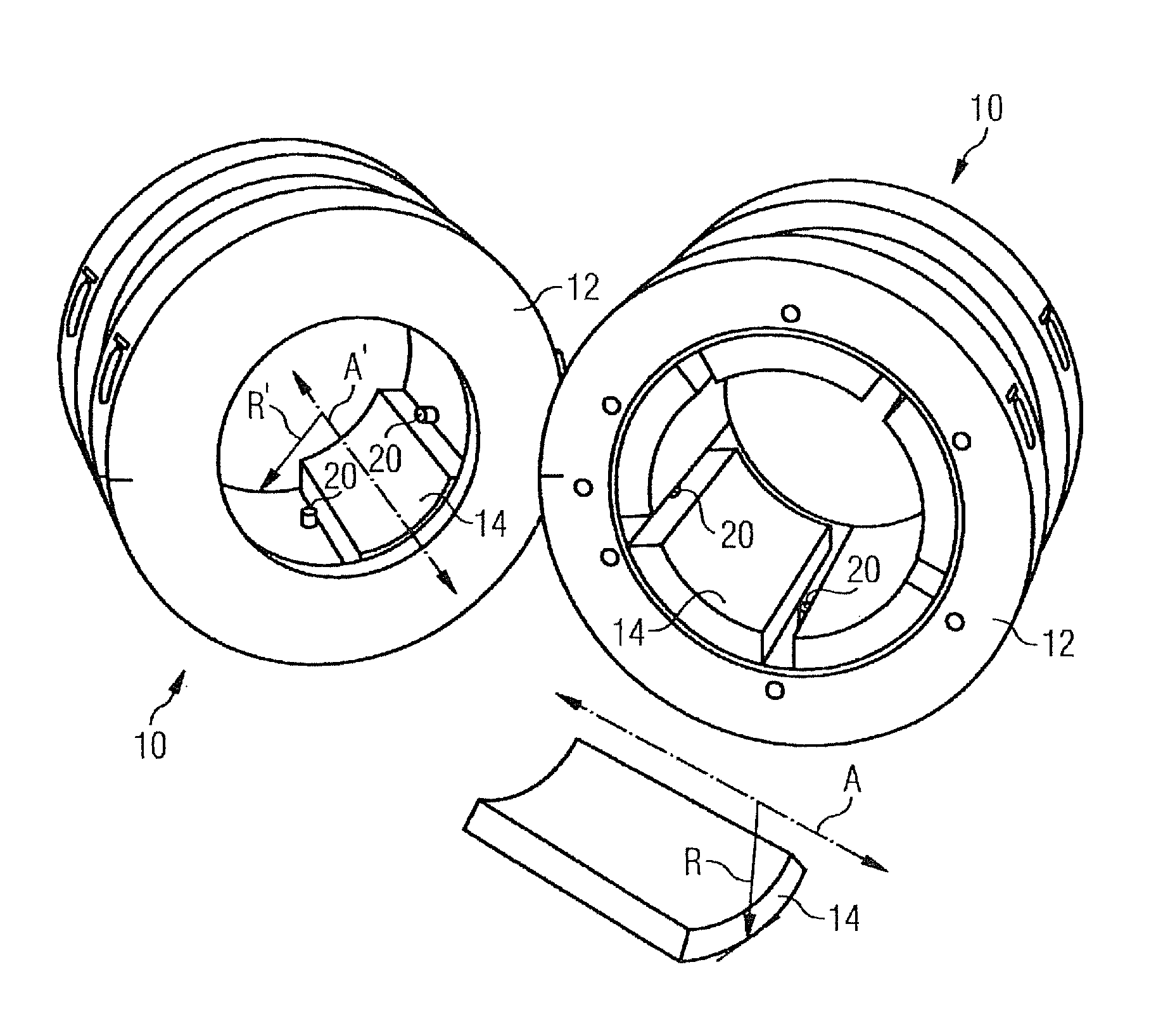
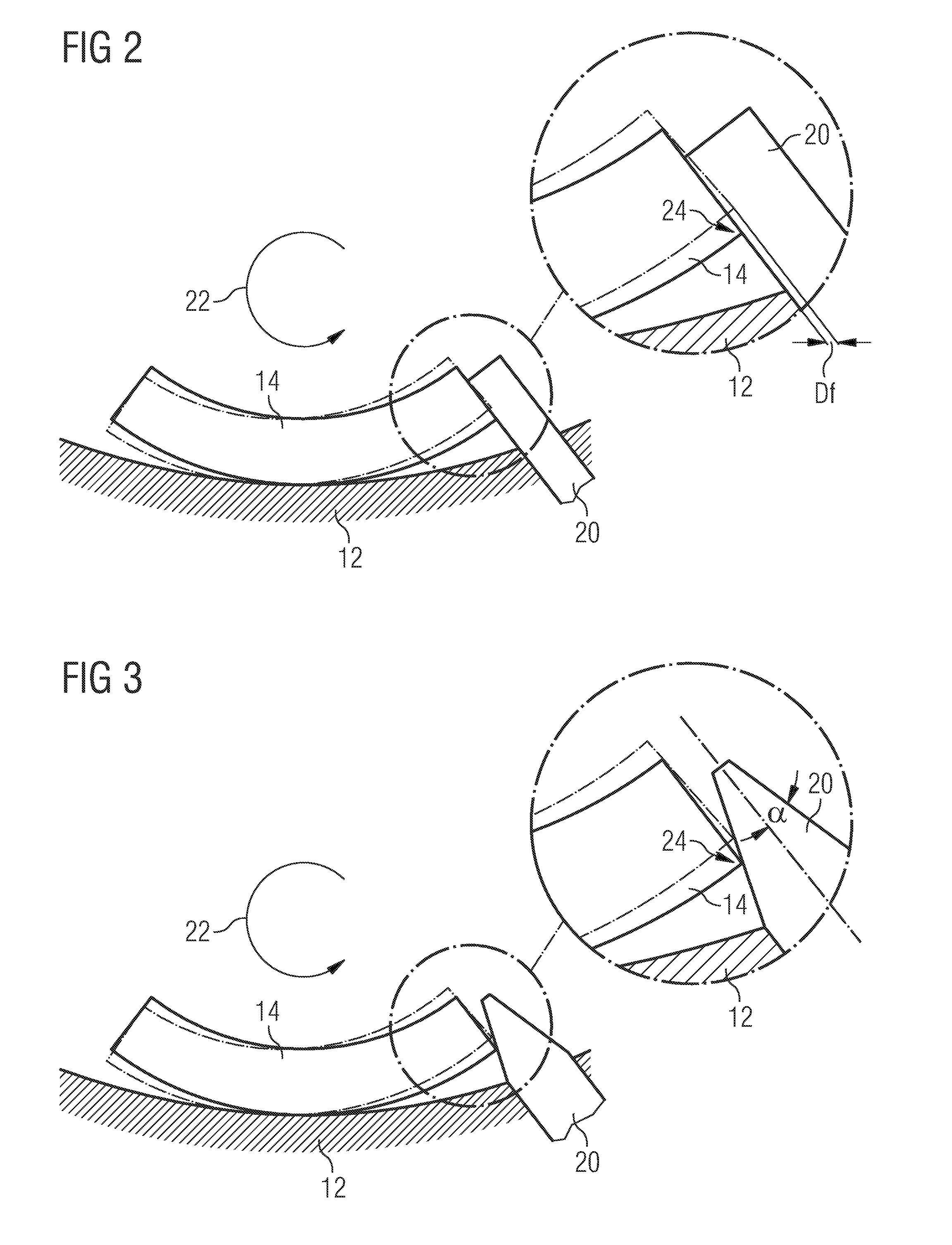
[0020]Referring to FIG. 3, in the first apparatus according to the present invention the cylindrical retaining pins 20 used have conical ends. The precise angle α of the inclined surface of the conical end depends on the path taken by radially outer edge 24 of the right hand side of tilting pad 14, as the pad rocks in unfettered manner between its solid and dotted line positions. The angle α should be such that the inclined surface follows the path taken by edge 24 as pad 14 so rocks.

[0021]By so forming the end of cylindrical retaining pin 20, edge 24 is permitted to move between its solid and dotted line positions without obstruction, thereby removing the need for slippage of pad 14 in the circumferential direction. In other words, in FIG. 2 the form of pin 20 is such as to permit only radial and not circumferential movement of edge 24 as pad 14 rocks, resulting in circumferential slippage of pad 14, whereas in FIG. 3 the form of pin 20 is such as to allow both radial and circumfer...


PUM


Abstract

An apparatus for supporting a rotating shaft comprising: a housing surrounding the shaft; interposed between the housing and the shaft a plurality of tilting pads which extend in contiguous manner circumferentially around the shaft, each tilting pad being able to rock in the rotation of the shaft; and interposed between each pair of adjacent tilting pads retaining means for preventing circumferential movement of the pads around the housing due to rotation of the shaft, wherein the physical relationship between at least one tilting pad and its adjacent retaining means is such that said rocking of the pad takes place without circumferential slippage of the pad around the housing.

Description

CROSS REFERENCE TO RELATED APPLICATIONS[0001]This application is a continuation-in-part of U.S. application Ser. No. 10 / 559,862, filed May 23, 2006 now U.S. Pat. No. 7,497,628. This application is the US National Stage of International Application No. PCT / EP2006 / 060593, filed Mar. 9, 2006 and claims the benefit thereof. The International Application claims the benefits of British application No. 0505162.8 filed Mar. 12, 2005. Both the International application and the British application are incorporated by reference herein in their entirety.FIELD OF INVENTION[0002]This invention relates to an apparatus for supporting a rotating shaft.[0003]More particularly, the invention relates to an apparatus for supporting a rotating shaft comprising: a housing surrounding the shaft; interposed between the housing and the shaft a plurality of tilting pads which extend in contiguous manner circumferentially around the shaft, each tilting pad being able to rock in the rotation of the shaft; and i...

Claims


Application Information

Patent Timeline
Patent Type & Authority Patents(United States)
IPC IPC(8): F16C17/03
CPCF16C17/03F16C2360/00
Inventor SHEPHERD, ANDREW
Owner SIEMENS AG
Why Eureka
Try Eureka