High efficiency grating coupling for light delivery in EAMR

a high-efficiency, light-delivering technology, applied in the field of magnetic recording heads, can solve the problems of increasing coercivity, increasing the coercivity of the grating, and reducing the grain size soon reaches the “superparamagnetic limit”, so as to reduce the problem of laser alignment, improve the coupling efficiency, and maximize the coupling of different portions

Active Publication Date: 2012-06-12
WESTERN DIGITAL TECH INC
View PDF19 Cites 176 Cited by
  • Summary
  • Abstract
  • Description
  • Claims
  • Application Information

AI Technical Summary

Benefits of technology

[0005]Various embodiments of the present invention solve the foregoing problems by providing a dual-grating waveguide coupler having a top grating and a bottom grating, wherein the top grating has a first period and a first etch depth, and the bottom grating has a second period and a second etch depth. The grating periods and etch depths are selected so as to maximize the coupling of different portions of incident electromagnetic (EM) radiation into the waveguide core layer. Such a dual-grating waveguide structure can provide an improved coupling efficiency and reduce the laser alignment problem by capturing a higher percentage of the incident EM radiation.

Problems solved by technology

This reduction in grain size soon reaches a “superparamagnetic limit,” at which point the magnetic grains become thermally unstable and incapable of maintaining their magnetization.
Increasing the magnetic anisotropy of the magnetic grains, however, increases their coercivity and therefore requires a stronger magnetic field to change the magnetic orientation of the grains (e.g., in a write operation).
Design challenges for these grating structures include improving their coupling efficiency and the difficulty in aligning a light source for high volume manufacturing processes.
Unfortunately, many EAMR heads have such poor coupling efficiency that they require costly high-power light sources and suffer from many heat-related reliability issues.

Method used


Image

  • High efficiency grating coupling for light delivery in EAMR
  • High efficiency grating coupling for light delivery in EAMR
  • High efficiency grating coupling for light delivery in EAMR

Examples


Embodiment Construction

[0019]In the following detailed description, numerous specific details are set forth to provide a full understanding of the present invention. It will be apparent, however, to one ordinarily skilled in the art that the present invention may be practiced without some of these specific details. In other instances, well-known structures and techniques have not been shown in detail to avoid unnecessarily obscuring the present invention. The word “exemplary” is used herein to mean “serving as an example, instance, or illustration.” Any embodiment or design described herein as “exemplary” is not necessarily to be construed as preferred or advantageous over other embodiments or designs.

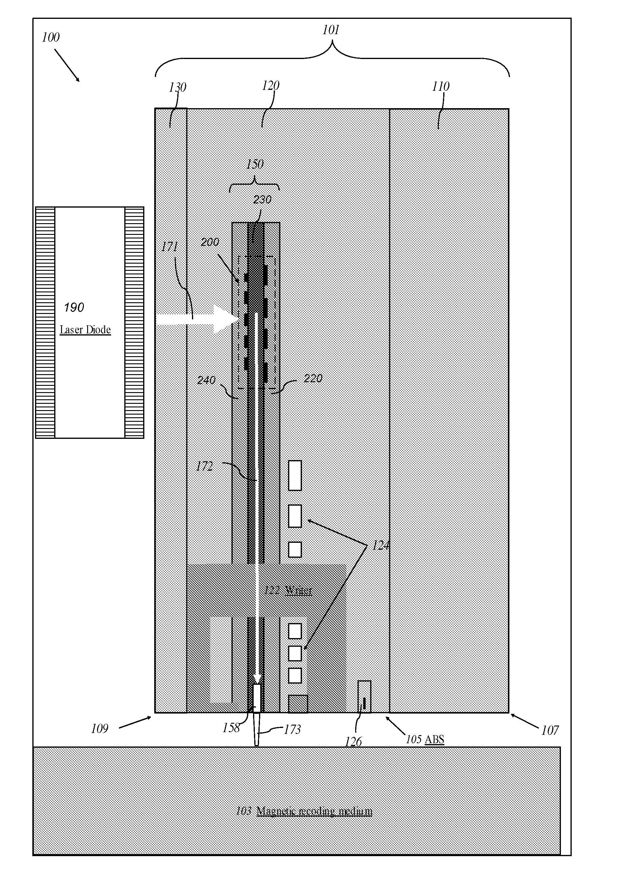
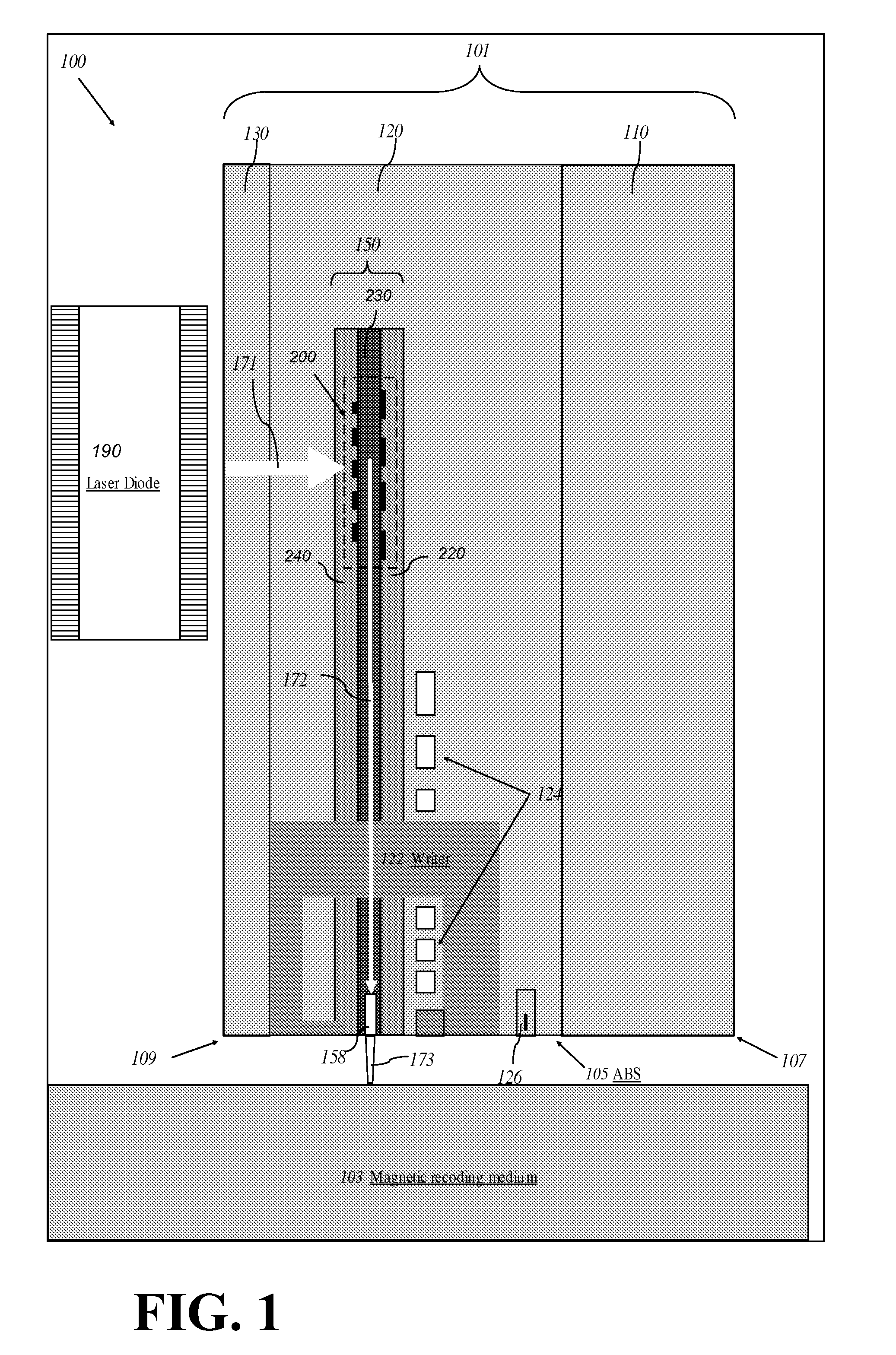
[0020]FIG. 1 is a cross-sectional diagram illustrating an exemplary EAMR head 100 comprising a dual-grating waveguide coupler 200 according to one aspect of the subject technology. The EAMR head 100 comprises a slider 101. The slider 101 comprises a substrate 110, a recorder / reader layer 120 disposed over th...


PUM

PropertyMeasurementUnit
etch depthaaaaaaaaaa
transverse-electricaaaaaaaaaa
transverse-magneticaaaaaaaaaa

Abstract

A magnetic head comprising a waveguide coupler for coupling incident electromagnetic (EM) radiation into a waveguide is disclosed. The waveguide coupler includes a bottom clad layer and a waveguide core layer formed above the bottom clad layer. An interface between the bottom clad layer and the waveguide core layer includes a first grating having a first period and a first etch depth, which are configured to couple a first portion of the incident EM radiation into the waveguide core layer. The waveguide coupler can further comprise a top clad layer formed above the waveguide core layer. An interface between the waveguide core layer and the top clad layer includes a second grating having a second period and a second etch depth. The second period and the second etch depth are configured to couple a second portion of the incident EM radiation into the waveguide core layer.

Description

FIELD OF THE INVENTION[0001]The present invention generally relates to magnetic recording heads and, in particular, relates to high efficiency grating coupling for light delivery in an energy-assisted magnetic recording (EAMR) head.BACKGROUND OF THE INVENTION[0002]To increase the areal storage density of a magnetic recording device, the recording layer thereof may be provided with smaller and smaller individual magnetic grains. This reduction in grain size soon reaches a “superparamagnetic limit,” at which point the magnetic grains become thermally unstable and incapable of maintaining their magnetization. The thermal stability of the magnetic grains can be increased by increasing the magnetic anisotropy thereof (e.g., by utilizing materials with higher anisotropic constants). Increasing the magnetic anisotropy of the magnetic grains, however, increases their coercivity and therefore requires a stronger magnetic field to change the magnetic orientation of the grains (e.g., in a writ...

Claims


Application Information

Patent Timeline
Patent Type & Authority Patents(United States)
IPC IPC(8): G02B6/34G11B11/00G11B11/24
CPCG02B6/124G02B6/34G02B6/4215G11B5/314G11B5/3163G11B2005/0021
Inventor LI, RUOLINHU, YUFENGTRAN, UT
Owner WESTERN DIGITAL TECH INC
Why Eureka
Try Eureka