Multi-fiber interface to photonic subassembly

a fiber array and sub-assembly technology, applied in the field of multi-fiber interface to photonic sub-assembly, can solve the problems of slowing down the penetration of fiber optic technology into other markets, high cost of manufacturing fiber optic interfaces, and high manufacturing cost of optical fiber interfaces

Active Publication Date: 2012-06-12
CISCO TECH INC
View PDF11 Cites 13 Cited by
  • Summary
  • Abstract
  • Description
  • Claims
  • Application Information

AI Technical Summary

Benefits of technology

[0011]The grooved lid and silicon photonic subassembly components are formed in accordance with the present invention to include registration features and alignment detents, respectively, that will mate when these two components are joined together and provide mechanical / optical alignment therebetween. The mating of the registration features and alignment detents has been found to provide alignment tolerances of approximately ±10 μm (in one exemplary embodiment) between the two components along all three axis. The grooved lid includes a plurality of underside grooves that will capture the optical fibers and refine their elevation from the above-mentioned 100 μm tolerance to approximately ±10 μm in the “z” direction as the fiber holder is slid into place over the grooved lid.
[0012]As the components are mated, the “x” direction position of the fiber is further constrained by a series of etched channels formed within an endface of the silicon photonic subassembly. The channels are precisely etched and aligned with waveguides formed on the subassembly to achieve positional tolerance on the order of, for example, ±1 μm in the “x” direction; therefore, as the fibers are guided into place from the fiber holder and along the grooved lid, the alignment tolerances will become tighter and tighter until the optical fibers enter into the well-defined spaces between the channels and become aligned with the optical waveguides. Final alignment tolerances are thus expected to be essentially the same in both the “y” and “z” directions (e.g., several microns, for example ±10 μm), and even less in the “x” direction (e.g., a few microns, for example ±2 μm). It is to be understood, however, that tighter tolerances can be achieved with the multiple piecepart configuration of the present invention by, for example, refining the tolerance requirements associated with the grooved lid component. The above exemplary values are considered to be exemplary only and provide an acceptable balance between cost and function, given the current state of the art associated with this technology.
[0013]It is an advantage of the interface structure of the present invention that the fiber holder and grooved lid may be formed of relatively inexpensive, common materials (e.g., polymers, ceramics, metals, and the like), providing a relatively inexpensive interface between a fiber array and a silicon photonic subassembly.

Problems solved by technology

However, optical fiber interfaces to electronic and optical networks tend to be expensive to manufacture—usually as a result of the difficulty associated with mounting optical transmitting and receiving devices on a substrate and separately aligning each one of these devices with an optical fiber.
However, the high cost of manufacturing fiber optic interfaces has been a barrier that has slowed the penetration of the fiber optic technology into other markets, such as local metropolitan area communication networks, for example.
Because of the small dimensions of optical fiber cores, aligning optical fibers with optical transmitting devices, which have aperture sizes that vary from approximately 2 to 10 microns, is difficult.
Obviously, the problem is particularly acute when the optical devices are to be aligned with single mode fiber.

Method used


Image

  • Multi-fiber interface to photonic subassembly
  • Multi-fiber interface to photonic subassembly
  • Multi-fiber interface to photonic subassembly

Examples


Embodiment Construction

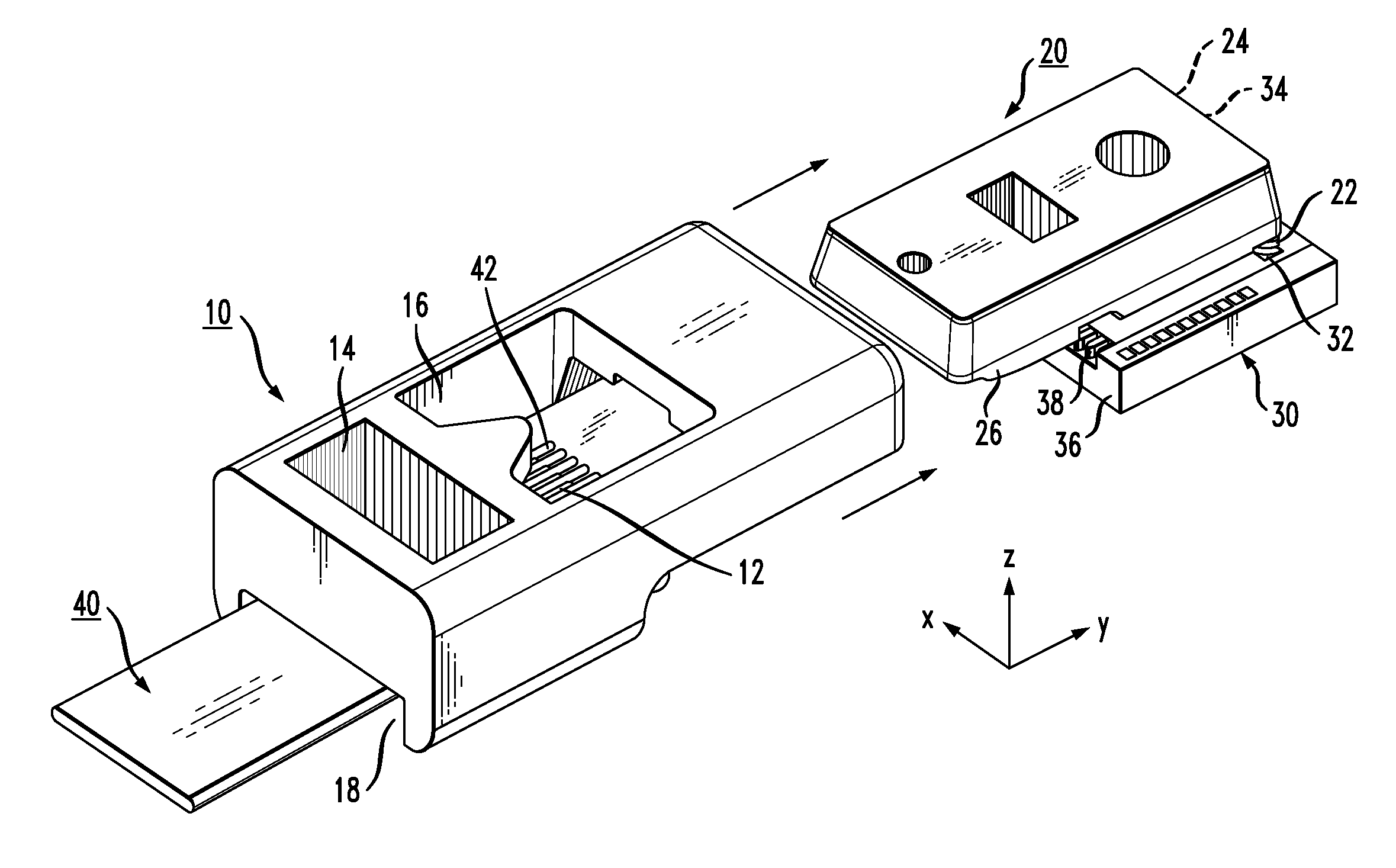
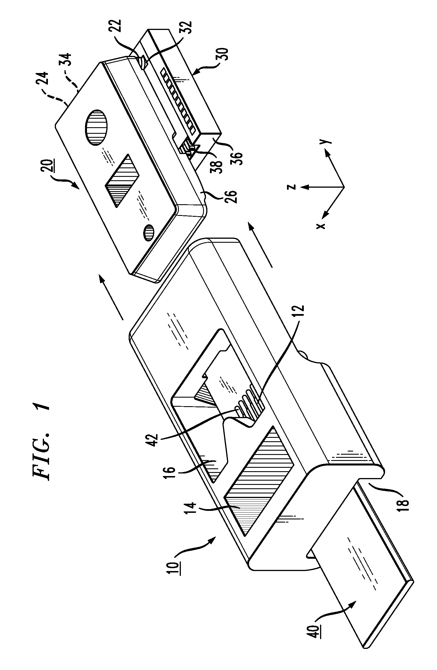
[0027]As will be described in detail hereinbelow, the present invention relates to a multiple piecepart alignment configuration for providing alignment between a fiber array and a planar photonic subassembly. In particular and as shown in FIG. 1, the invention consists of three separate components: a box-shaped fiber holder 10, a grooved lid 20 and a silicon photonic subassembly 30, with an xyz set of coordinates also shown in FIG. 1. In use, a fiber array 40 is inserted in fiber holder 10, where the individual fibers forming the array are introduced to sequentially tighter alignment tolerances until being ultimately aligned with waveguides (not shown) formed on silicon photonic subassembly 30. An alignment on the order of ±2 μm in the x-axis direction, in combination with a ±10 μm y-axis / z-axis (longitudinal / vertical) alignment has been achieved with one exemplary embodiment of the configuration of the present invention.

[0028]The three separate components used to provide this align...


PUM


Abstract

A multiple piecepart alignment and attachment configuration for mating a fiber array (or even a single fiber) with a silicon photonic subassembly utilizes ever-tightening alignment tolerances to align the fiber array with a similar array of waveguides (or other devices) formed within the photonic subassembly. A box-shaped fiber holder is formed to include a plurality of grooves within its bottom interior surface to initially support the fiber array. A separate piecepart in the form of a lid is mated to, and aligned with, the silicon photonic subassembly. The lid is formed to include registration features on its underside that fit into alignment detents formed in the top surface of the silicon photonic subassembly upon attachment. The lid also includes a number of grooves formed on its underside that will capture the top surface of the fibers as the fiber holder is slide into place over the lid. The grooves within the lid function to tighten the pitch of the fiber array and ultimately control the lateral and vertical alignment between the fiber array and the subassembly. The subassembly is also formed to include etched channels along the endface (the channels aligned with optical waveguides / devices in the substrate) to mate with the fiber holder, where the optical fibers are ultimately positioned within the channels so as to be in alignment with the optical waveguides / devices.

Description

CROSS-REFERENCE TO RELATED APPLICATIONS[0001]This application claims the benefit of U.S. Provisional Application No. 61 / 196,286, filed Oct. 16, 2008.TECHNICAL FIELD[0002]The present invention relates to a system for mechanically aligning a fiber array to a photonic subassembly and, more particularly, to a multiple piecepart alignment configuration where a fiber array is presented to consecutively tighter and tighter alignment tolerances until the array is ultimately presented to, and aligned with, a photonic subassembly.BACKGROUND OF THE INVENTION[0003]Inasmuch as optical fibers are characterized by a wide transmission bandwidth and relatively low attenuation, they are particularly well-suited for communications applications. However, optical fiber interfaces to electronic and optical networks tend to be expensive to manufacture—usually as a result of the difficulty associated with mounting optical transmitting and receiving devices on a substrate and separately aligning each one of...

Claims


Application Information

Patent Timeline
Patent Type & Authority Patents(United States)
IPC IPC(8): G02B6/30G02B6/38
CPCG02B6/423G02B6/4249G02B6/4292G02B6/3636G02B6/3652G02B6/3692G02B6/43G02B6/4201
Inventor BAUGH, BRENTON A.
Owner CISCO TECH INC
Why Eureka
Try Eureka