Systems and methods for remote monitoring of signals sensed by an implantable medical device during an MRI

a medical device and signal technology, applied in the field of implantable medical devices, can solve the problems of interference with the operation of any medical device, joule heating, inappropriate sensing and pacing, etc., and achieve the effect of reducing the influence of mri fields

Active Publication Date: 2012-06-12
PACESETTER INC
View PDF21 Cites 38 Cited by
  • Summary
  • Abstract
  • Description
  • Claims
  • Application Information

AI Technical Summary

Benefits of technology

[0010]In accordance with a first general embodiment, methods are provided for use by an implantable medical device for implant within a patient, wherein the method is for use during an MRI procedure. In one example, signals are sensed within the patient during the MRI procedure while filtering the sensed signals to reduce the influence of MRI fields on the sensed signals and then the signals are transmitted to an external monitoring system during the MRI procedure so that the signals can thereby be remotely monitored during the MRI. The signals sensed by the implanted device and then transmitted to the external system include electrophysiological signals such as intracardiac electrogram (IEGM) signals. The signals sensed by the device and then transmitted to the ext

Problems solved by technology

A significant problem with MRI is that its strong magnetic fields can interfere with the operation of any medical devices, particularly pacemakers or ICDs, implanted within the patient.
When patients with pacers or ICDs are exposed to MRI fields, RF fields of the MRI can induce currents along the conduction paths causing excessive current to flow into tissue or blood through tip or ring electrodes resulting in Joule heating.
Excessive power dissipation might damage the tissues around pacing electrodes causing inappropriate sensing and pacing and posing risks to the patient.
Additionally, the powerful gradient fields of an MRI s

Method used


Image

  • Systems and methods for remote monitoring of signals sensed by an implantable medical device during an MRI
  • Systems and methods for remote monitoring of signals sensed by an implantable medical device during an MRI
  • Systems and methods for remote monitoring of signals sensed by an implantable medical device during an MRI

Examples


Embodiment Construction

[0031]The following description includes the best mode presently contemplated for practicing the invention. The description is not to be taken in a limiting sense but is made merely to describe general principles of the invention. The scope of the invention should be ascertained with reference to the issued claims. In the description of the invention that follows, like numerals or reference designators will be used to refer to like parts or elements throughout.

Overview of MRI-Responsive Systems and Procedures

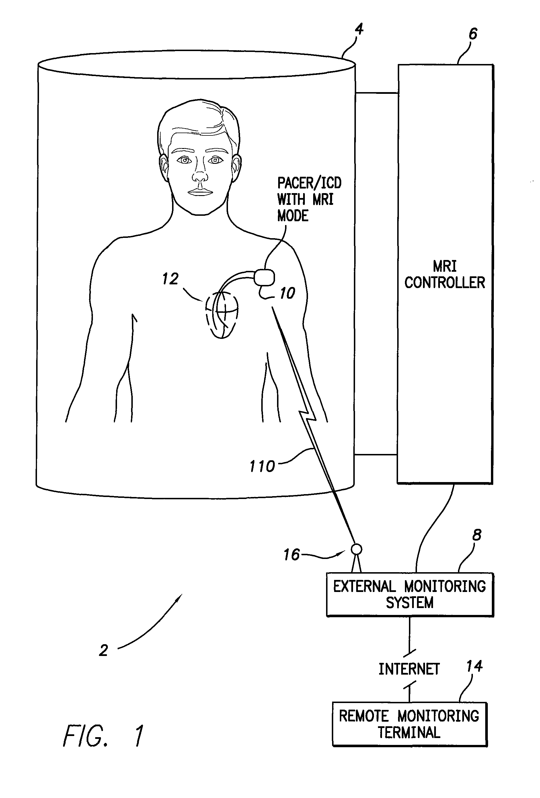
[0032]FIG. 1 illustrates an overall MRI system 2 having an MRI machine 4 operative to generate MRI fields during an MRI procedure for examining a patient. The MRI machine operates under the control of an MRI controller 6, which controls the strength and orientation of the fields generated by the MRI machine and derives images of portions of the patient therefrom, in accordance with otherwise conventional techniques. MRI machines and imaging techniques are well known and will not...


PUM


Abstract

Systems and methods are provided for allowing an implantable medical device, such as pacemaker, to properly sense electrophysiological signals and hemodynamic signals within a patient during a magnetic resonance imaging (MRI) procedure. Systems and methods are also provided for allowing the implantable medical device to transmit the sensed data to an external monitoring system during the MRI procedure so that attending medical personnel can closely monitor the health of the patient and the operation of the implantable device during the MRI. These improvements provide the attending personnel with information needed to determine whether the MRI should be suspended in response to induced tachyarrhythmias or other adverse conditions within the patient.

Description

CROSS-REFERENCE TO RELATED APPLICATIONS[0001]This application is related to U.S. patent application Ser. No. 10 / 973,862, filed Oct. 25, 2004, entitled “Electromagnetic Interference Safe Modes for Implantable Electronic Devices”, now abandoned, which is fully incorporated by reference herein, including the appendices thereof.FIELD OF THE INVENTION[0002]The invention generally relates to implantable medical devices, such as pacemakers or implantable cardioverter / defibrillators (ICDs), and to external diagnostics systems for use therewith and, in particular, to techniques for monitoring and displaying electrophysiological signals and hemodynamic signals sensed within a patient by an implantable medical device during a magnetic resonance imaging (MRI) procedure.BACKGROUND OF THE INVENTION[0003]MRI is an effective, non-invasive magnetic imaging technique for generating sharp images of the internal anatomy of the human body, which provides an efficient means for diagnosing disorders such ...

Claims


Application Information

Patent Timeline
IPC IPC(8): A61N1/08
CPCA61N1/3718A61B5/686A61B5/7203A61B5/0031A61B5/02055A61B5/0422A61B5/02028A61B5/287
Inventor MIN, XIAOYIMOUCHAWAR, GABRIEL A.
Owner PACESETTER INC
Why Eureka
Try Eureka