System and method for calibrating cardiac pressure measurements derived from signals detected by an implantable medical device

a technology of cardiac pressure and signal, which is applied in the field of implantable medical devices, can solve the problems of insufficient blood flow to meet the needs of tissues, heart failure, and loss of propulsive power, and achieve the effect of precise calibration of estimation procedures, accurate slope and baseline values

Active Publication Date: 2012-06-19
PACESETTER INC
View PDF35 Cites 33 Cited by
  • Summary
  • Abstract
  • Description
  • Claims
  • Application Information

AI Technical Summary

Benefits of technology

[0025]Thus, the second exemplary embodiment exploits the recognition that, within at least some patients, slope and baseline conversion factors are not independent of one another but are instead linearly correlated. Within such patients, the slope and baseline values can be re-calibrated without requiring “two-point” calibration, i.e. without requiring at least two sets of calibration values, such as a first set of calibration values (Z1, LAP1) detected while the patient is at rest and a second set of calibration values (Z2, LAP2) detected while the patient is subject to a condition significantly affecting cardiac pressure. Rather, it is sufficient to obtain one new pair of calibration values (e.g. Z1, LAP1) to recalibrate both slope and baseline, thereby allowing for more convenient recalibration.
[0036]One particular advantage of converting acute slope values to chronic slope values is that acute values are more easily calibrated than chronic values. Initial calibration of the slope value is preferably performed in a medical center under the supervision of a clinician. For example, a Swan-Ganz catheter may be used to measure PCWP values for use in calibration along with simultaneous impedance measurements. Typically, the patient is in the acute state while being assessed within the medical center and hence acute calibration values are readily obtained. To instead obtain chronic calibration values would require that the patient rest for an extended period of time within the medical center so that the measured impedance values are representative of the chronic steady state values when both the intra-vascular and interstitial fluid compartment volumes have equilibrated. In other words, the adjustment technique allows an acute slope value to be conveniently obtained during an outpatient medical center procedure using impedance measurements made in the acute state. The acute slope value is then converted to a chronic slope value for use in estimating LAP within the patient at times when the patient is in the chronic steady state.
[0040]Insofar as circadian immittance signals are concerned, such signals preferably include a first set of immittance signals obtained during the day within the patient in an upright posture and a second set of immittance signals obtained during the night within the patient in a supine posture. As noted, immittance values sensed within a patient can vary from day to night based on the amount of fluid within the interstitial spaces within the thorax. Accordingly, by detecting both day and night immittance signals, the circadian variation can be exploited to more precisely calibrate the estimation procedure. As such, the implantable device is preferably equipped with detection circuitry capable of making frequently immittance measurements throughout the day to permit tracking of circadian variations in immittance.

Problems solved by technology

Heart failure is a debilitating disease in which abnormal function of the heart leads to inadequate blood flow to fulfill the needs of the tissues and organs of the body.
Typically, the heart loses propulsive power because the cardiac muscle loses capacity to stretch and contract.
Often, the ventricles do not adequately fill with blood between heartbeats and the valves regulating blood flow become leaky, allowing regurgitation or back-flow of blood.
The impairment of arterial circulation deprives vital organs of oxygen and nutrients.
Fatigue, weakness and the inability to carry out daily tasks may result.
As heart failure progresses, it tends to become increasingly difficult to manage.
Even the compensatory responses it triggers in the body may themselves eventually complicate the clinical prognosis.
If the oxygen supply falls short of the growing demand, as it often does, further injury to the heart may result, typically in the form of myocardial ischemia or myocardial infarction.
The additional muscle mass may also stiffen the heart walls to hamper rather than assist in providing cardiac output.
Often, electrical and mechanical dyssynchronies develop within the heart such that the various chambers of the heart no longer beat in a synchronized manner, degrading overall cardiac function.
A particularly severe form of heart failure is congestive heart failure (CHF) wherein the weak pumping of the heart or compromised filling leads to build-up of fluids in the lungs and other organs and tissues.
Hence, LAP estimates could be provided to the physician via diagnostic displays, rather than raw impedance signal values, which the physicians might find difficult to interpret.
However, LAP is a difficult parameter to detect since it is not clinically appealing to place a blood pressure sensor directly in the left atrium due to the chronic risk of thromboembolic events, as well as risks associated with the trans-septal implant procedure itself.
Although electrical impedance can be used to estimate LAP, it is difficult to reliably calibrate such impedance-based estimation techniques.
That is, it can be difficult to accurately and reliably convert detected electrical impedance values into actual LAP values.
However, there is insufficient time to permit any significant changes to occur within the interstitial fluid compartment since the physiologic change is short lived and the original physiologic state is rapidly restored.

Method used


Image

  • System and method for calibrating cardiac pressure measurements derived from signals detected by an implantable medical device
  • System and method for calibrating cardiac pressure measurements derived from signals detected by an implantable medical device
  • System and method for calibrating cardiac pressure measurements derived from signals detected by an implantable medical device

Examples


Embodiment Construction

[0089]The following description includes the best mode presently contemplated for practicing the invention. The description is not to be taken in a limiting sense but is made merely for the purpose of describing the general principles of the invention. The scope of the invention should be ascertained with reference to the issued claims. In the description of the invention that follows, like numerals or reference designators will be used to refer to like parts or elements throughout.

Overview of Implantable Medical System

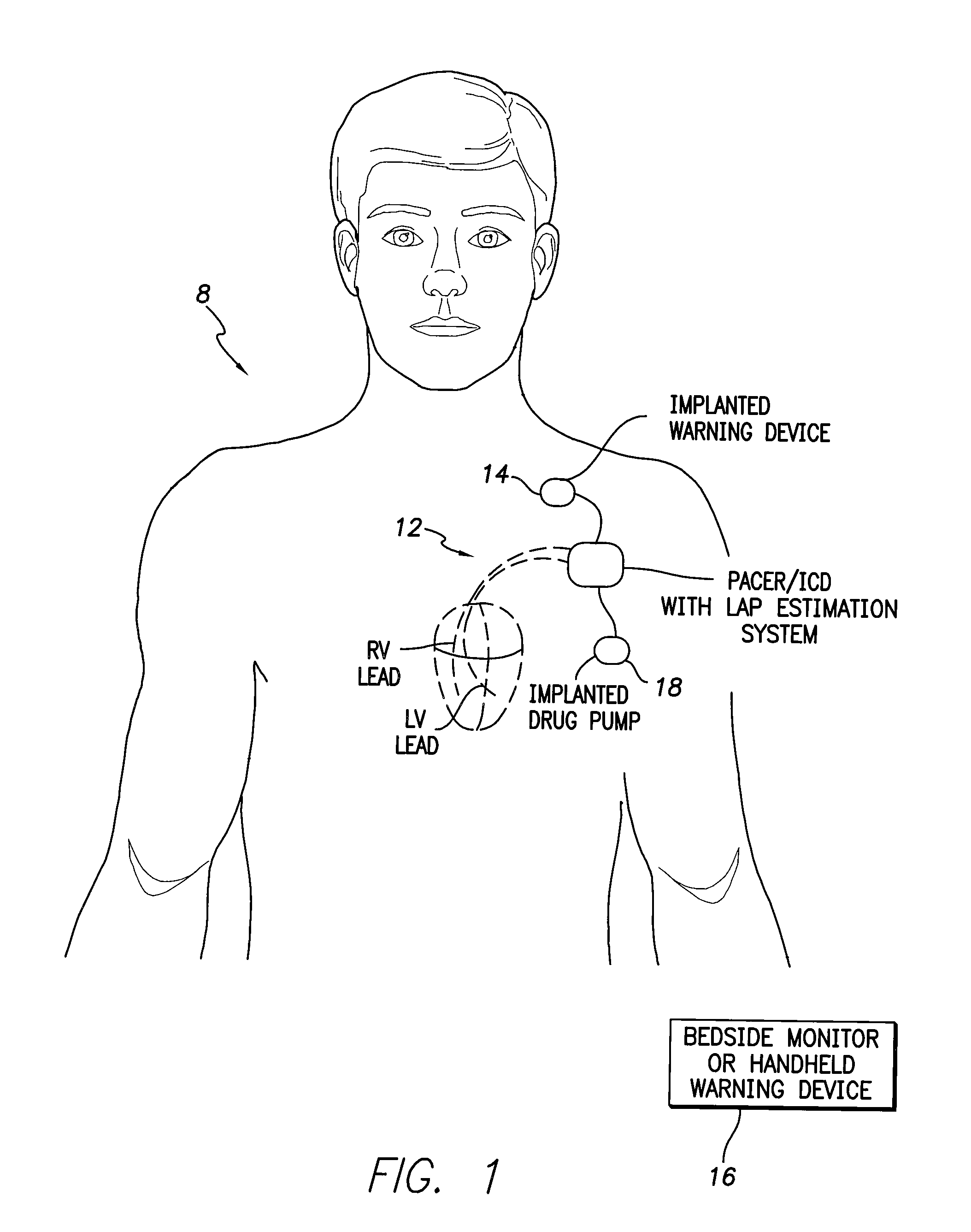
[0090]FIG. 1 provides a stylized representation of an exemplary implantable pacing medical system 8 capable of detecting electrical impedance signals and estimating LAP based on the impedance signals. To this end, implantable system 8 includes a pacer / ICD 10 or other cardiac stimulation device that incorporates internal components (shown individually in FIG. 20) for detecting one or more impedance signals using electrodes mounted to a set of sensing / pacing leads 12 an...


PUM


Abstract

Various techniques are provided for calibrating and estimating left atrial pressure (LAP) using an implantable medical device, based on impedance, admittance or conductance parameters measured within a patient. In one example, default conversion factors are exploited for converting the measured parameters to estimates of LAP. The default conversion factors are derived from populations of patients. In another example, a correlation between individual conversion factors is exploited to allow for more efficient calibration. In yet another example, differences in thoracic fluid states are exploited during calibration. In still yet another example, a multiple stage calibration procedure is described, wherein both invasive and noninvasive calibration techniques are exploited. In a still further example, a therapy control procedure is provided, which exploits day time and night time impedance / admittance measurements.

Description

RELATED APPLICATIONS[0001]This application is a Continuation-in-Part of U.S. patent application Ser. No. 11 / 559,235, filed Nov. 13, 2006, now U.S. Pat. No. 7,794,404, entitled “System and Method for Estimating Cardiac Pressure Using Parameters Derived from Impedance Signals Detected by an Implantable Medical Device” and claims priority therefrom.[0002]This application is also related to U.S. Provisional Patent Application No. 60 / 787,884, filed Mar. 31, 2006 entitled “Tissue Characterization Using Intracardiac Impedances with an Implantable Lead System.”[0003]This application is also related to the following U.S. patent application Ser. Nos.:11 / 558,101, filed Nov. 9, 2006;11 / 557,851, filed Nov. 8, 2006;11 / 557,870, filed Nov. 8, 2006;11 / 557,882, filed Nov. 8, 2006; and11 / 558,088, filed Nov. 9, 2006; each entitled “Systems and Methods to Monitor and Treat Heart Failure Conditions.” Each of the foregoing applications is fully incorporated by reference herein, including the appendices th...

Claims


Application Information

Patent Timeline
Patent Type & Authority Patents(United States)
IPC IPC(8): A61B5/0205A61B5/021A61B5/02
CPCA61B5/0215A61B5/053A61B5/6846
Inventor GUTFINGER, DAN E.EIGLER, NEAL L.PANESCU, DORINWHITING, JAMES S.
Owner PACESETTER INC
Why Eureka
Try Eureka