Optical fiber structure with filtering thin film

a thin film, optical fiber technology, applied in the direction of optics, optical waveguide light guides, instruments, etc., can solve the problems of fiber components disadvantageous in easily being damaged, wavelength drift, and expensive price, and achieve low cost, simple and easy fabrication, and reduce the loss of optical coupling in free space

Inactive Publication Date: 2012-06-19
IND TECH RES INST
View PDF9 Cites 2 Cited by
  • Summary
  • Abstract
  • Description
  • Claims
  • Application Information

AI Technical Summary

Benefits of technology

[0009]Accordingly, the present invention is directed to an optical fiber structure with a filtering thin film. With the provided optical fiber structure, a simpler and easier fabrication and low cost are expected. In addition, with the structure for example, the polarization of the light in the fiber can be controlled, the light transmission wavelength is controllable, the different fiber segments can be directly connected to each other in adhering way so as to reduce the optical coupling loss of the light in free space and the displacement loss caused by shake, the anti-reflection layers are somewhat saved for fabricating and the fiber is capable of transmitting a higher power.

Problems solved by technology

The currently available optical fiber component goods, such as fiber polarizer having a reflective component with an fiber Bragg grating (FBG) for selecting wavelength or a protector for pumping light source, have disadvantage of expensive price and fabrication difficulty.
However, the fiber engineered and fabricated with the above-mentioned approach is easily affected by thermal effect, causing wavelength drifted.
In addition, the above-mentioned fiber component is disadvantageous in easily being damaged, inability of being bent and expensive price.
The fiber provided by U.S. Pat. No. 7,440,653 has the same disadvantage as the above-mentioned one that it is likely thermally effected to thereby make wavelength drifted, easily damaged, inability to be bent and expensive.

Method used


Image

  • Optical fiber structure with filtering thin film
  • Optical fiber structure with filtering thin film
  • Optical fiber structure with filtering thin film

Examples


Embodiment Construction

[0022]Reference will now be made in detail to the present preferred embodiments of the invention, examples of which are illustrated in the accompanying drawings. Wherever possible, the same reference numbers are used in the drawings and the description to refer to the same or like parts.

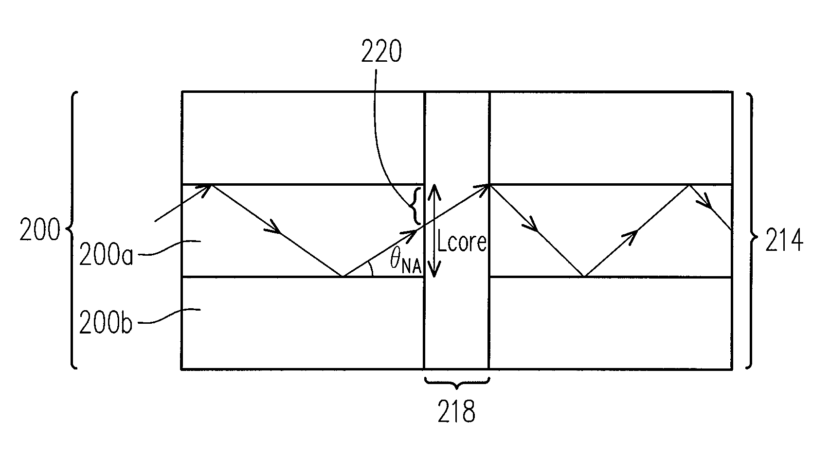
[0023]The present invention provides an optical fiber structure with a filtering thin film. The optical fiber structure has advantages of simplicity of the fabrication process flow and low relative cost. The optical fiber structure can be used, for example, to control the light polarization in a fiber and to control the light transmission wavelength as well. In addition, by directly connecting the fiber in adhering way, the present invention can further reduce the optical coupling loss of the light in free space and the displacement loss caused by shake; the anti-reflection layers are also somewhat saved for fabricating and the fiber is capable of transmitting a higher power.

[0024]Several embodiments...


PUM


Abstract

An optical fiber with filtering thin film includes a first ferrule having a first through hole and a first contact surface. A first fiber is disposed into the first through hole, extending to the first contact surface. A first interface coupling material is between the first ferrule and the first fiber. A second ferrule has a second through hole and a second contact surface. A second fiber is disposed into the second through hole, extending to the second contact surface. A second interface coupling material is between the second ferrule and the second fiber. The first contact surface and the second contact surface are parallel and have an included tilt angle from a perpendicular transverse plane of first fiber. An optical filtering film is disposed between the first contact surface and the second contact surface. The first fiber and the second fiber are aligned.

Description

CROSS-REFERENCE TO RELATED APPLICATION[0001]This application claims the priority benefit of Taiwan application serial no 98125929, filed on Jul. 31, 2009. The entirety of the above-mentioned patent application is hereby incorporated by reference herein and made a part of specification.BACKGROUND OF THE INVENTION[0002]1. Field of the Invention[0003]The present invention generally relates to an optical fiber structure, and more particularly, to an optical fiber structure with a filtering thin film.[0004]2. Description of Related Art[0005]The currently available optical fiber component goods, such as fiber polarizer having a reflective component with an fiber Bragg grating (FBG) for selecting wavelength or a protector for pumping light source, have disadvantage of expensive price and fabrication difficulty.[0006]Among the related traditional technologies, for example, the one disclosed by U.S. Pat. No. 6,832,025 is based on that an optical gritting with a long cycle period is disposed ...

Claims


Application Information

Patent Timeline
Patent Type & Authority Patents(United States)
IPC IPC(8): G02B6/10
CPCG02B6/2726G02B6/29368G02B6/276
Inventor LIN, SHIH-TINGJHANG, YAO-WUNSU, HSIN-CHIAHUANG, CHIEN-MINGHU, CHIEH
Owner IND TECH RES INST
Why Eureka
Try Eureka