Engine driven power generator

a technology of engine-driven power generators and power generators, which is applied in the direction of machines/engines, mechanical energy handling, mechanical equipment, etc., can solve the problems of reducing the weight and size of the engine-driven power generator, and achieve the effect of reducing the number of steps and reducing the weight and siz

Active Publication Date: 2012-06-26
HONDA MOTOR CO LTD
View PDF15 Cites 6 Cited by
  • Summary
  • Abstract
  • Description
  • Claims
  • Application Information

AI Technical Summary

Benefits of technology

[0006]In view of the foregoing prior art problems, it is an object of the present invention to provide an improved engine-driven power generator which has a reduced weight and size and can be assembled with a reduced number of steps.
[0008]Because the single cooling fan for cooling both the engine and the power generation section is provided on the flywheel that is disposed between the crankcase of the engine and the power generation section, a fan for cooling the engine and a fan for cooling the power generation section, which had to be separate components in the prior art, can be integrated as the single cooling fan, and thus, the engine-driven power generator of the present invention can be significantly reduced in weight and size. Further, because there is no need to attach separate engine cooling and power-generation-section cooling fans individually to predetermined portions of the engine-driven power generator, the present invention can reduce the necessary number of steps for assembling the engine-driven power generator and thus achieve an enhanced productivity of the engine-driven power generator.
[0009]Further, in the present invention, the cooling fan is disposed radially inwardly of the flywheel. Thus, separate engine cooling and power-generation-section cooling fans need not be provided axially outwardly of the flywheel, and thus, the flywheel and the cooling fan can be provided as a single flywheel / cooling fan unit which has a small width substantially equal to the width of the flywheel. In this way, the flywheel / cooling fan unit in the engine-driven power generator of the invention can be constructed compactly.
[0011]Namely, in the engine-driven power generator arranged in the aforementioned manner, air can be taken into the power-generation-section-cooling-air intake passage, by rotation of the small-diameter cooling fan, to thereby cool the power generation section. Simultaneously, by rotation of the small- and large-diameter cooling fans, air directed via the power-generation-section-cooling-air intake passage and engine-cooling-air intake passage to the cooling fans can be delivered to the downstream cooling air delivery passage and then to the engine to thereby cool the engine.
[0012]Namely, with the single flywheel / cooling fan unit (i.e., fan-equipped flywheel) including the small- and large-diameter cooling fans, the present invention can cool not only the power generation section but also the engine. As a result, the weight and size of the engine-driven power generator can be significantly reduced.

Problems solved by technology

However, because the cooling fan of the engine and the cooling fan of the power generation section are provided separately from each other in the prior art engine-driven power generator, the engine-driven power generator requires many component parts to make the engine cooling fan and power-generation-section cooling fan, which would thus hinder reduction in weight and size of the engine-driven power generator.
Further, the prior art engine-driven power generator would require many steps for individually attaching the engine cooling fan and power-generation-section cooling fan to predetermined portions of the power generator.

Method used


Image

  • Engine driven power generator
  • Engine driven power generator
  • Engine driven power generator

Examples


Embodiment Construction

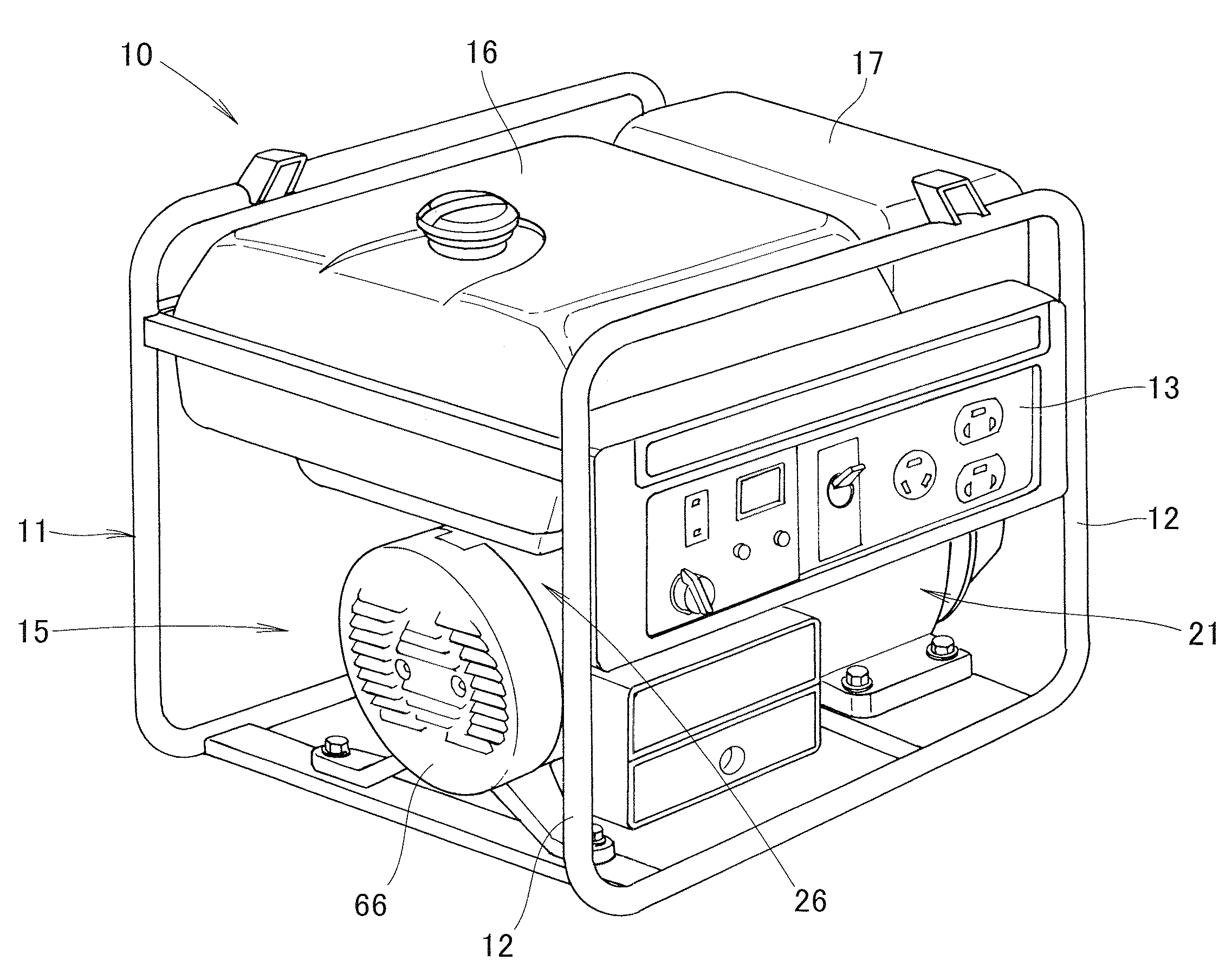
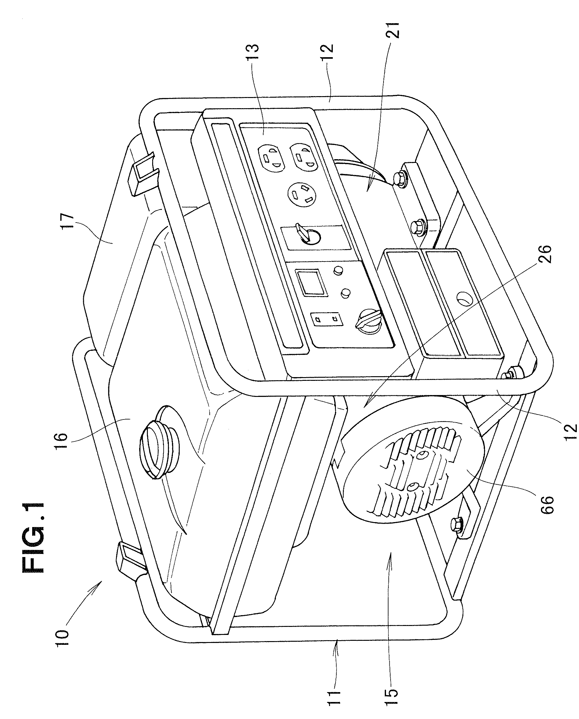
[0021]FIG. 1 is a perspective view showing an embodiment of an engine-driven power generator of the present invention. The engine-driven power generator 10 comprises: a frame 11 constructed of a plurality of struts 12 etc. and having a substantial parallelepiped shape; a control panel 13 disposed between a pair of the struts 12; an engine / power generation section unit 15; and a fuel tank 16 and muffler 17 provide over the engine / power generation section unit 15. The control panel 13 has accommodated therein various electric and electronic component parts to constitute an engine control section and an electric power take-out section.

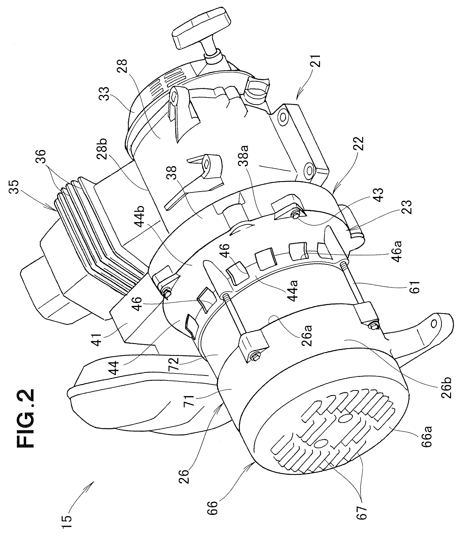
[0022]FIG. 2 is a perspective view showing the engine / power generation section unit 15, and FIG. 3 is an exploded perspective view showing the engine / power generation section unit 15.

[0023]The engine / power generation section unit 15 includes an engine 21, a first fan cover 22 attached to the engine 21, a second fan cover 23 attached to the first fan cover...


PUM


Abstract

In an engine-driven power generator, a fan-equipped flywheel and a drive shaft of a power generation section are connected to a crankshaft of an engine, and the power generation section is driven by the drive shaft being driven via the crankshaft. The fan-equipped flywheel is disposed between a crankcase of the engine and the power generation section, and small- and large-diameter cooling fans for cooling the engine and power generation section are provided on the fan-equipped flywheel.

Description

CROSS-REFERENCE TO RELATED APPLICATION[0001]This application claims the priority of Japanese Application No. 2008-066742, filed Mar. 14, 2008, the entire specification, claims and drawings of which are incorporated herewith by reference.FIELD OF THE INVENTION[0002]The present invention relates to an engine-driven power generator which has a flywheel and a drive shaft of a power generation section connected to a crankshaft of an engine, and which generates electric power by the drive shaft being rotated via the crankshaft.BACKGROUND OF THE INVENTION[0003]Among the conventionally-known engine-driven power generators are ones which have a drive shaft of a power generation section connected concentrically connected to a crankshaft of an engine, and in which a fan for cooling the engine and a fan for cooling the power generation section are provided separately from each other. More specifically, the engine cooling fan is provided on a portion of the engine opposite from the power generat...

Claims


Application Information

Patent Timeline
Patent Type & Authority Patents(United States)
IPC IPC(8): F01P1/00
CPCF02B63/04H02K5/20H02K7/1815H02K9/06F02B63/042F02B63/044F02B63/048H02K5/207
Inventor HATSUGAI, TSUTOMUYAMADA, MAKOTOSASAJIMA, TAKESHIONODERA, TAIYO
Owner HONDA MOTOR CO LTD
Why Eureka
Try Eureka