Magnetic shielding for portable detector

a portable, magnetic shielding technology, applied in the field of digital radiographic detectors, to achieve the effect of reducing weight and siz

Active Publication Date: 2011-09-20
CARESTREAM HEALTH INC
View PDF12 Cites 3 Cited by
  • Summary
  • Abstract
  • Description
  • Claims
  • Application Information

AI Technical Summary

Benefits of technology

[0049]An advantage of the present invention is that it provides EMI shielding for a portable DR detector with reduced weight and size. This would allow the portable DR detector to be used as a retrofit with existing x-ray equipment that may have sources of low frequency magnetic fields that would otherwise interfere with and prevent the use of conventional DR technology.

Problems solved by technology

One further complication for EMI shielding relates to the need for external openings that allow cable connections, signal transmission, fasteners, and the like.

Method used


Image

  • Magnetic shielding for portable detector
  • Magnetic shielding for portable detector
  • Magnetic shielding for portable detector

Examples


Embodiment Construction

[0070]The following is a detailed description of the preferred embodiments of the invention, reference being made to the drawings in which the same reference numerals identify the same elements of structure in each of the several figures.

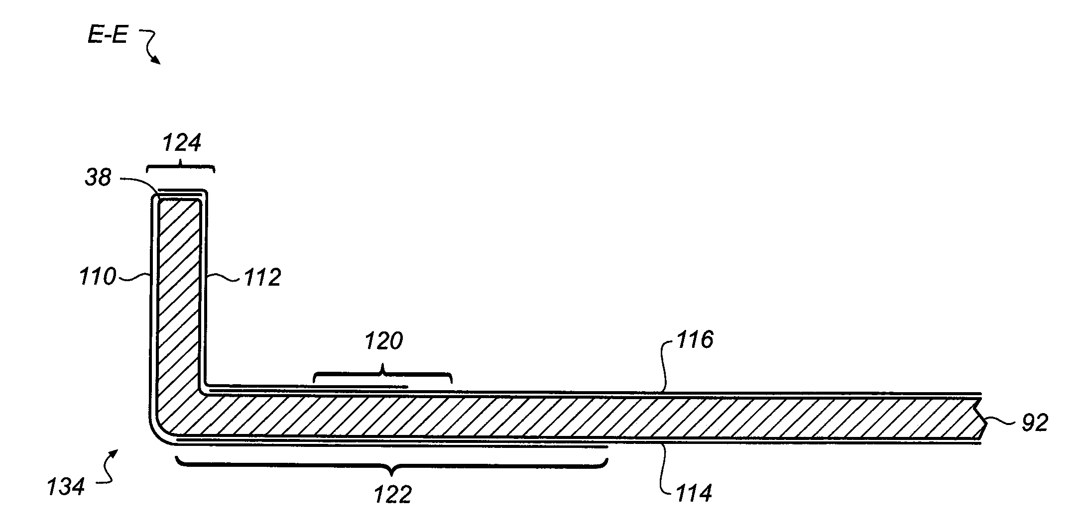
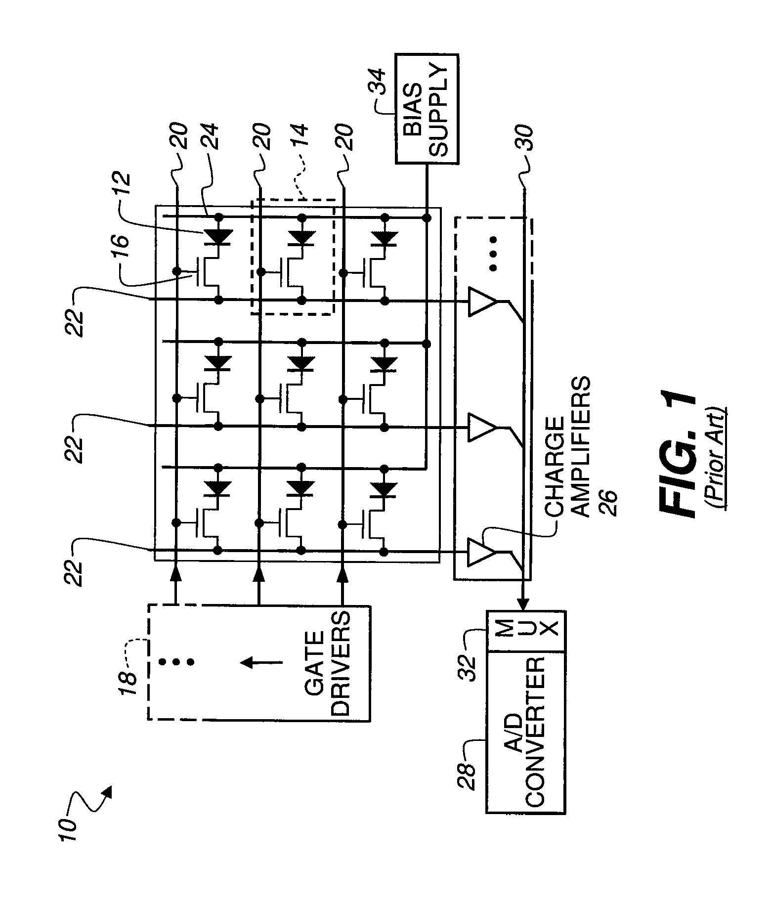
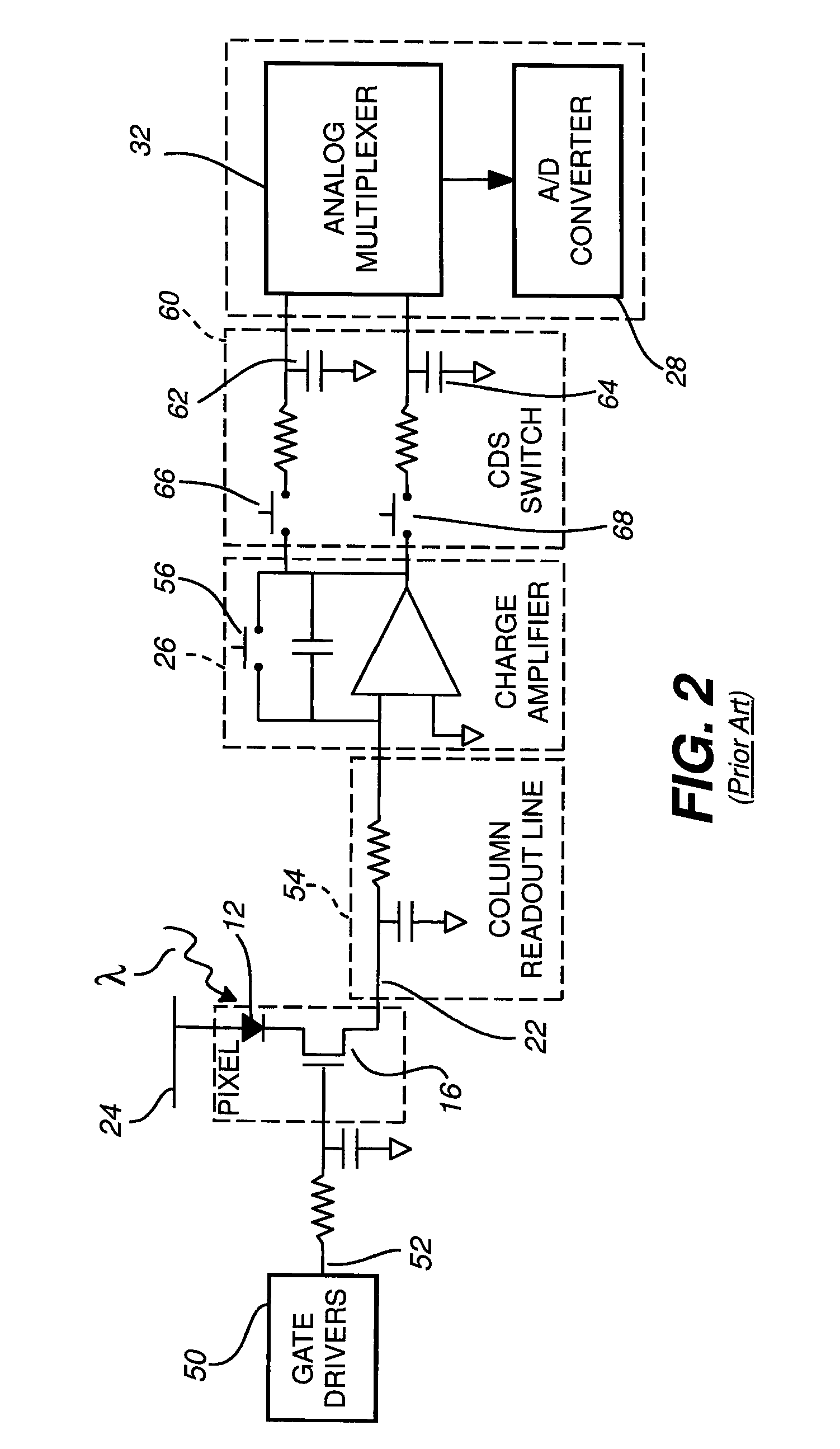
[0071]As noted in the background section, high impedance sensing circuitry can be very susceptible to low frequency magnet fields, particularly if their input signal lines link a magnetic flux. By the nature of the DR panel composition and function, high-impedance readout circuits are expected to be primarily located near edges of the detector.

[0072]In the context of the present disclosure, the terms “top” and “bottom” or “vertical” are not are not intended to be limiting and are not used to define a particular orientation of a radiographic detector or its components, but are intended primarily to indicate the positional relationships of opposing surfaces or other features relative to each other.

[0073]In the context of the present disclosure, “high ...


PUM


Abstract

A digital radiographic detector has a detector panel that forms digital image data according to radiation exposure energy. An enclosure houses the detector panel, formed from an electrically conductive material and having a base with an inner base surface and an outer base surface and having, along its perimeter, one or more side walls that extend orthogonally from the inner base surface. A base magnetic shield extends as a layer of nanocrystalline material across at least one of the inner base surface and the outer base surface. A cover is formed from a non-conductive material and has a cover magnetic shield of a layer of a metallic alloy bonded to an inner surface. A side wall magnetic shield extends along one or more surfaces of the one or more side walls, wherein the side wall magnetic shield has at least one of the nanocrystalline material or the metallic alloy.

Description

FIELD OF THE INVENTION[0001]The invention relates generally to digital radiographic detectors and more particularly to magnetic shielding for portable digital radiographic detectors.BACKGROUND OF THE INVENTION[0002]Digital radiography (DR) is increasingly preferred as an alternative to both film-based and Computed Radiography (CR) imaging technologies that use photosensitized film or photostimulable storage phosphors to obtain image content from radiation exposure. With digital radiography, the radiation exposure energy that is captured on radiation sensitive layers is converted, pixel by pixel, to electronic image data which is then stored in memory circuitry for subsequent read-out and display on suitable electronic image display devices. One driving force in the success of digital radiography is the ability to rapidly visualize and communicate stored images via data networks to one or more remote locations for analysis and diagnosis. With DR imaging, this can be done without the ...

Claims


Application Information

Patent Timeline
Patent Type & Authority Patents(United States)
IPC IPC(8): H01J31/49
CPCG03B42/02G01T1/2018H01L27/14658
Inventor HAWVER, JEFFERY R.DANIELS, STEVEN D.ASENTO, ROBERT
Owner CARESTREAM HEALTH INC
Why Eureka
Try Eureka