Lifting/skidding device with a permanent magnet synchronous motor

Inactive Publication Date: 2017-01-12
SIEMENS AG
View PDF8 Cites 2 Cited by
  • Summary
  • Abstract
  • Description
  • Claims
  • Application Information

AI Technical Summary

Benefits of technology

[0012]In this context it is further advantageous, according to further possible embodiments of the present invention, if said planetary gear is the only gear between said motor and said lifting/skidding mechanism. In this way, an even more advantageous shape (basically a cylindrical shape) of the resulting motor gear unit may be obtained.
[0013]According to the fact that said motor and said gear are arranged in a single housing or said motor/gear is arranged in t

Problems solved by technology

The resulting dimensions and the weight of the motor gear units as well

Method used


Image

  • Lifting/skidding device with a permanent magnet synchronous motor
  • Lifting/skidding device with a permanent magnet synchronous motor
  • Lifting/skidding device with a permanent magnet synchronous motor

Examples


Embodiment Construction

[0024]The illustration in the drawing is schematically. It is noted that in different figures, similar or identical elements or features are provided with the same reference signs or with reference signs, which are different from the corresponding reference signs only within the first digit. In order to avoid unnecessary repetitions elements or features which have already been elucidated with respect to a previously described embodiment are not elucidated again at a later position of the description.

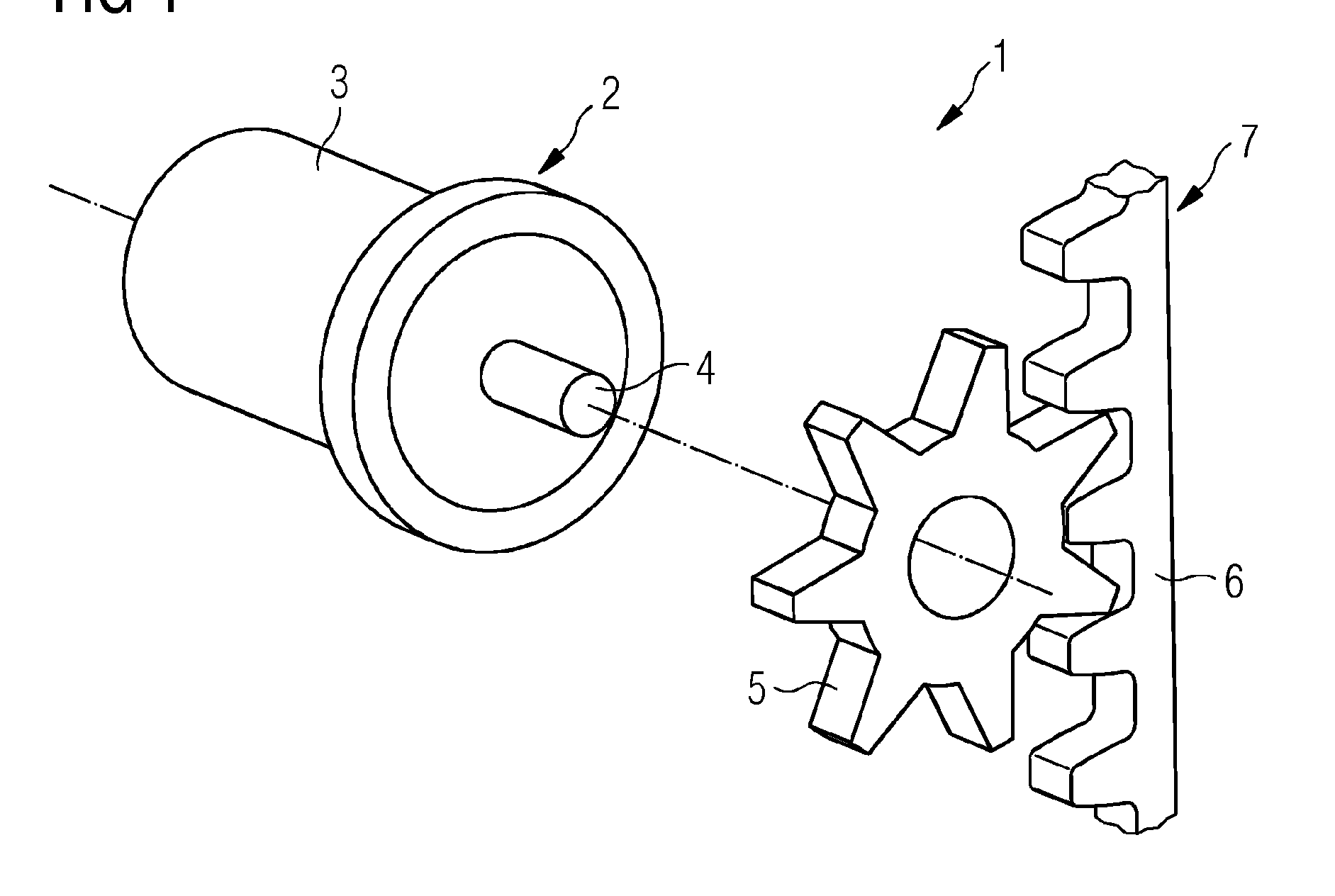
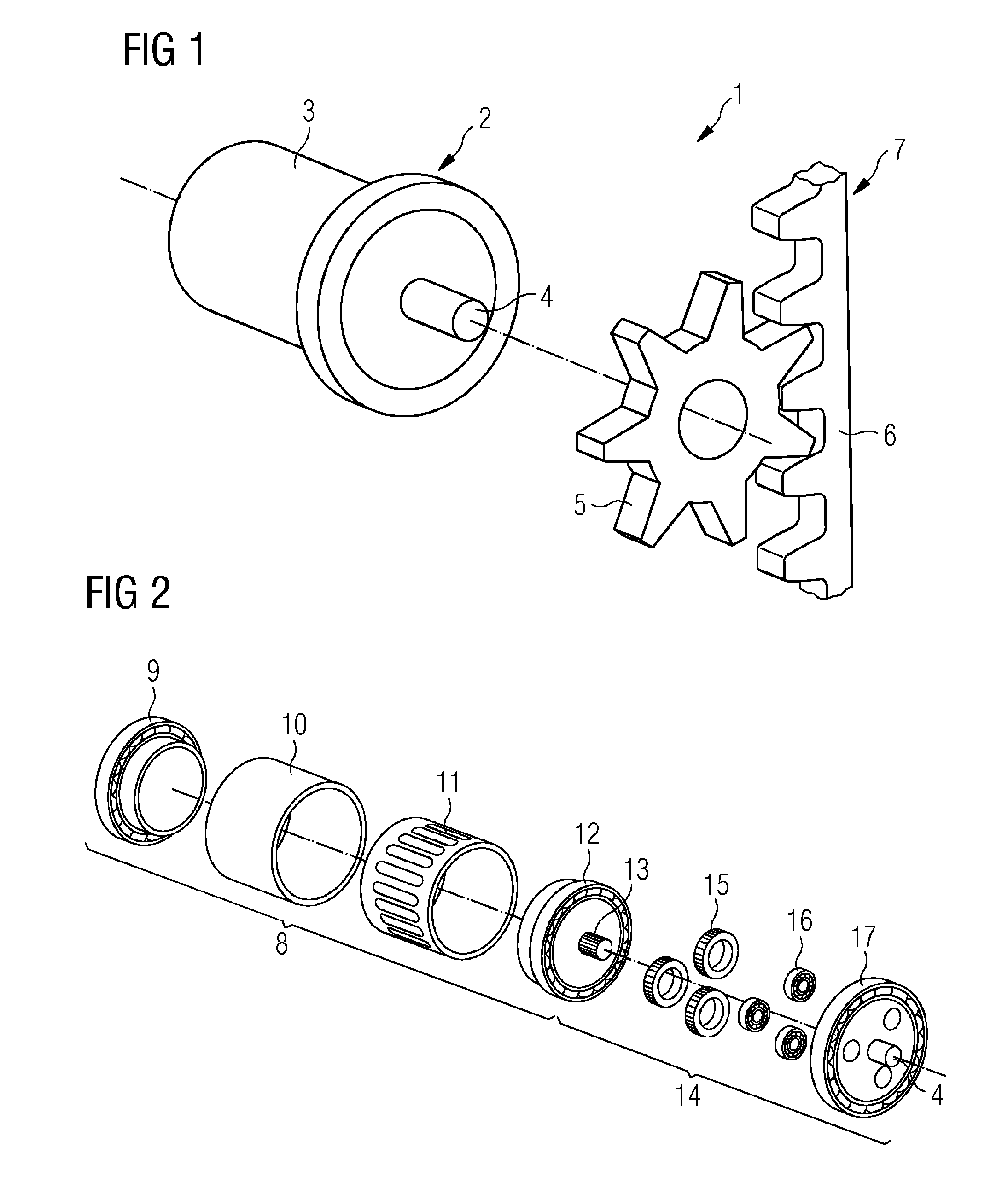
[0025]FIG. 1 shows a schematic oblique view of an exemplary lifting / skidding device 1, comprising a motor gear unit 2 with a housing 3 and a gear output 4. The housing 3 is cylindrical. The gear output 4 protrudes axially from the housing 3 of the motor gear unit 2. Furthermore the lifting / skidding device 1 comprises a pinion 5 coupled to the motor gear unit 2 by means of the gear output 4 and a gear rack 6 engaged with said pinion 5. The pinion 5 and the gear rack 6 are part of a liftin...


PUM


Abstract

A lifting/skidding device includes an electric motor, a gear coupled to the motor and a lifting/skidding mechanism coupled to the gear, wherein the motor is embodied as a permanent magnet synchronous machine. The lifting/skidding device is adapted for lifting/skidding an offshore construction.

Description

CROSS REFERENCE TO RELATED APPLICATIONS[0001]This application is the US National Stage of International Application No. PCT / EP2014 / 075355 filed Nov. 24, 2014, and claims the benefit thereof. The International Application claims the benefit of European Application No. EP14157552 filed Mar. 4, 2014. All of the applications are incorporated by reference herein in their entirety.FIELD OF INVENTION[0002]The present invention relates to a lifting / skidding device, comprising an electric motor, a gear coupled to said motor and a lifting / skidding mechanism coupled to said gear. Moreover, the present invention relates to a usage of a lifting / skidding device of the kind above.ART BACKGROUND[0003]A lifting / skidding device and a usage as presented above are generally known. An electrically driven hoisting or jacking system generally is used to lower, to lift / hoist (vertical movement) and / or to pull or to tow (horizontal movement) objects. For example, rack and pinion jacking drives or hoist rope...

Claims


Application Information

Patent Timeline
IPC IPC(8): B66F9/24H02K21/12H02K7/116B66F9/20B66D1/12
CPCB66F9/24B66F9/205H02K21/12H02K7/116B66D1/12
Inventor HOOYMANS, RICKVAN DER DOES, TACOVAN DER GROEP, ROGIER
Owner SIEMENS AG
Why Eureka
Try Eureka