Patient monitoring device

a monitoring device and patient technology, applied in the field of patient-worn monitoring devices, can solve the problems of electrical contact, adhesion and adhesion problems of conventional patient-worn sensors, and achieve the effect of reducing weight and siz

Pending Publication Date: 2022-08-11
MURATA VIOS INC
View PDF0 Cites 0 Cited by
  • Summary
  • Abstract
  • Description
  • Claims
  • Application Information

AI Technical Summary

Benefits of technology

[0021]To overcome the problems described above, preferred embodiments of the present invention provide patient-monitoring devices that achieve significantly reduced weigh

Problems solved by technology

Conventional patient-worn sensors can have p

Method used


Image

  • Patient monitoring device
  • Patient monitoring device
  • Patient monitoring device

Examples


Embodiment Construction

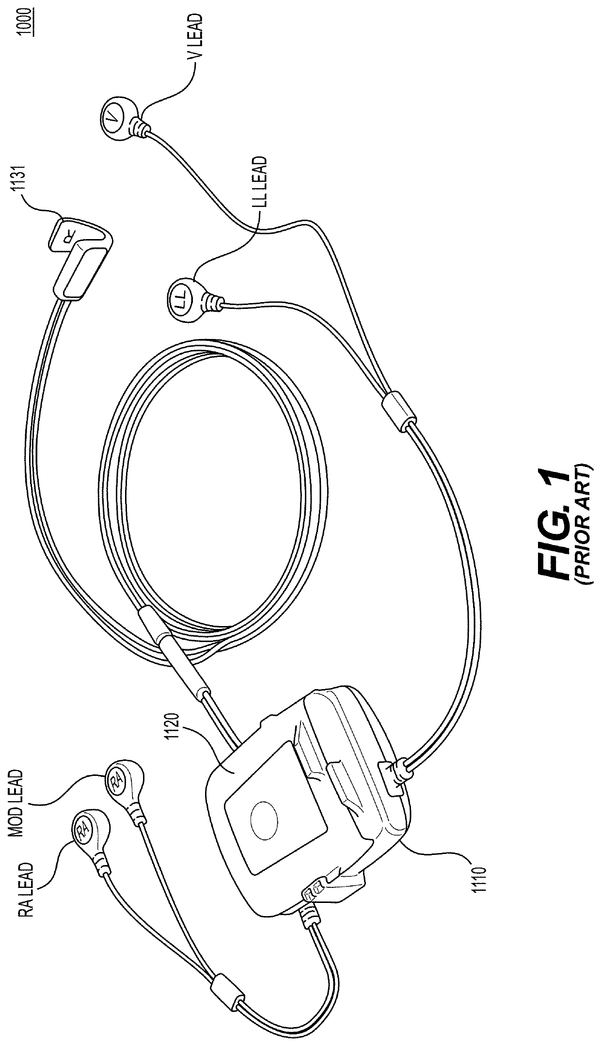
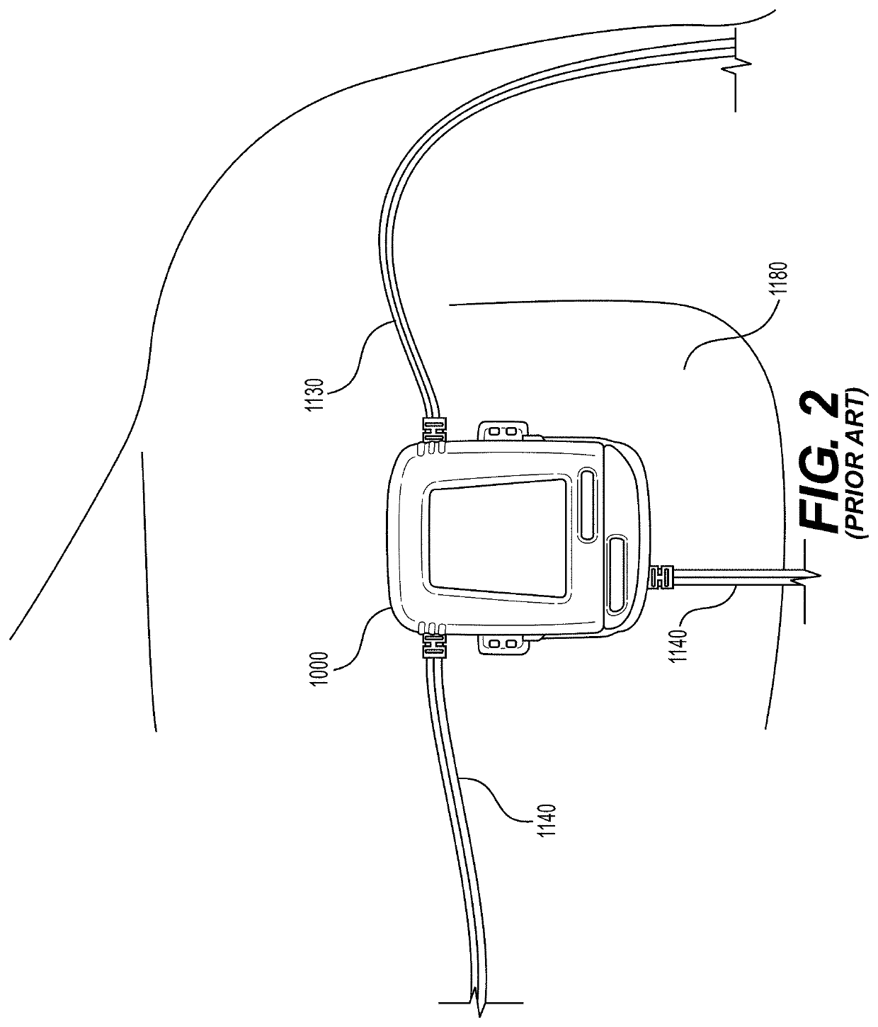
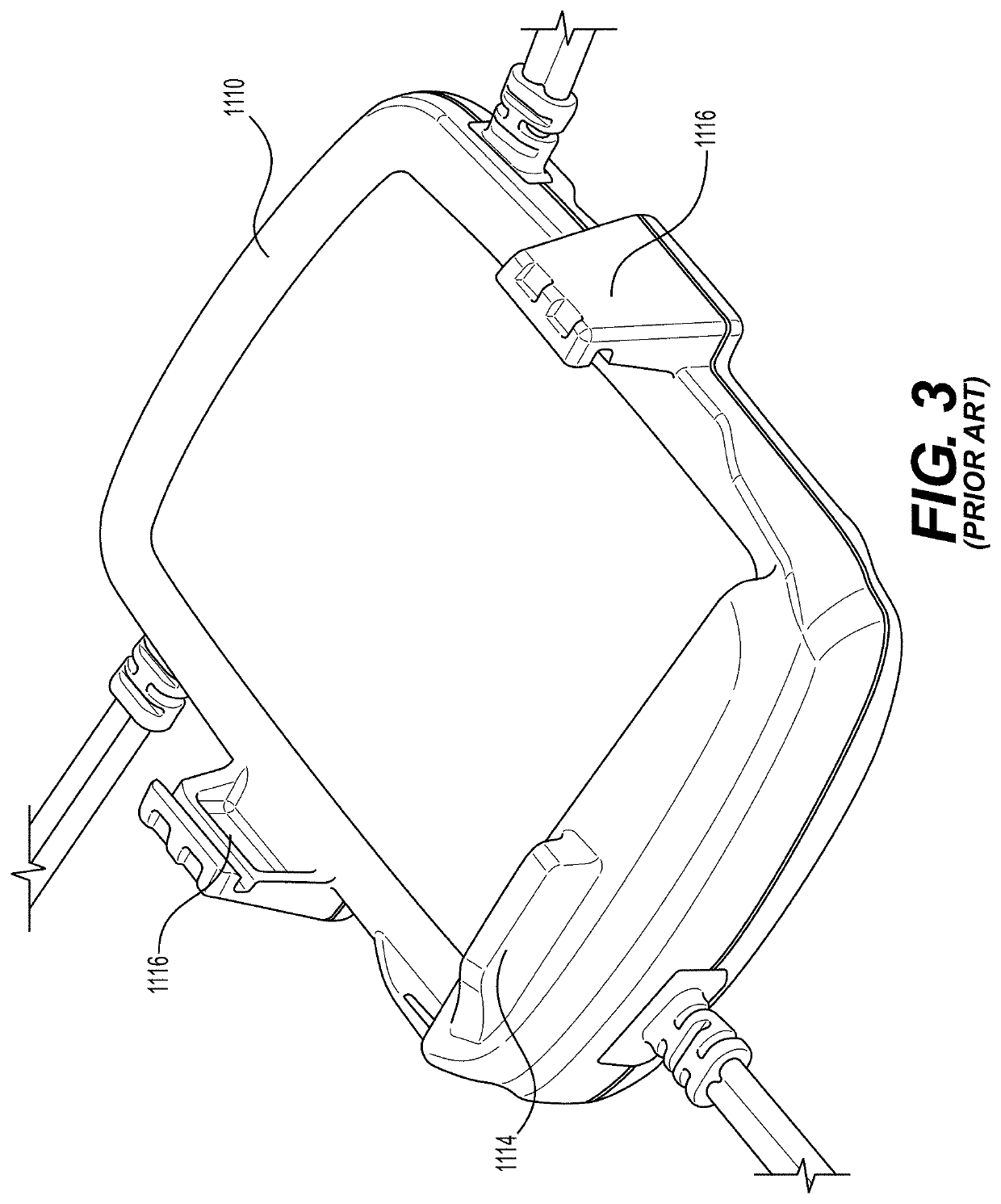
[0055]FIG. 16 shows a patient monitoring device 100 according to a preferred embodiment of the present invention. In the example shown in FIG. 16, the chest device 110 of the patient monitoring device 100 can be attached to the chest of a patient. However, the patient monitoring device 100 can be attached to one or more other areas on the patient's body. The patient monitoring device 100 can detect, record, store, and transmit various vital signs and other information of the patient. For example, the patient monitoring device 100 can include several adherent electrodes (see, for example, FIG. 28) that contact the patient's skin to measure various biological information, vital signs, and patient information including, but not limited to, heart rhythm, heart rate, blood pressure, body temperature, respiratory rate, blood oxygenation, blood glucose level, hydration levels, perspiration, and bio-impedance. The patient monitoring device 100 can also track patient motion, movement, activi...


PUM


Abstract

A patient-monitoring device includes a housing including a first opening, a snap located in the first opening to connect to an electrode through the first opening, and a dielectric potting compound covering the snap. A method of manufacturing a patient-monitoring device includes attaching a wire to a snap, providing a housing, providing a substrate including a connector and circuitry components, installing the snap into the housing, installing the substrate into the housing, providing a dielectric potting compound into the housing such that the dielectric potting compound covers the snap and the substrate, and curing the dielectric potting compound.

Description

CROSS REFERENCE TO RELATED APPLICATIONS[0001]This application claims benefit to U.S. Patent Application No. 63 / 148,296, filed on Feb. 11, 2021, the entire contents of which are hereby incorporated herein by reference.BACKGROUND OF THE INVENTION1. Field of the Invention[0002]The present invention relates to a patient-worn monitoring device that is temporarily affixed or adhered to a patient's skin.2. Description of the Related Art[0003]Many different types of patient monitoring systems require a direct electrical interface to the skin of a patient. In some applications, the direct electrical interface to the patient's skin is to sense electrical signals present at that skin location; while in other applications, the direct electrical interface is to apply an electrical current stimulation signal at that skin location. Therefore, the patient monitoring systems typically require a patient-worn sensor assembly that detects, records, and communicates patient data. As such, the patient-wo...

Claims


Application Information

Patent Timeline
IPC IPC(8): A61B5/274A61B5/256A61B5/257A61B5/00A61B5/024A61B5/021A61B5/145A61B5/01A61B5/08A61B5/11
CPCA61B5/274A61B2562/166A61B5/257A61B5/6823A61B5/024A61B5/021A61B5/14532A61B5/01A61B5/0816A61B5/14542A61B5/4875A61B5/1118A61B5/1116A61B2560/0214A61B5/256
Inventor HIRATA, ATSUHIKOMYERS, RACHELKONDO, NOBUHIRO
Owner MURATA VIOS INC
Why Eureka
Try Eureka