Ink tank and printing apparatus
a printing apparatus and a technology applied in the field of a printing head and a printing head, can solve the problems of reducing the amount of ink available, increasing the volume of the porous member itself, and increasing the porosity, and achieving the effect of high volume efficiency
- Summary
- Abstract
- Description
- Claims
- Application Information
AI Technical Summary
Benefits of technology
Problems solved by technology
Method used
Image
Examples
first embodiment
[0050]A first embodiment of the present invention will be described below with reference to the accompanying drawings.
Structure of Inkjet Printing Apparatus
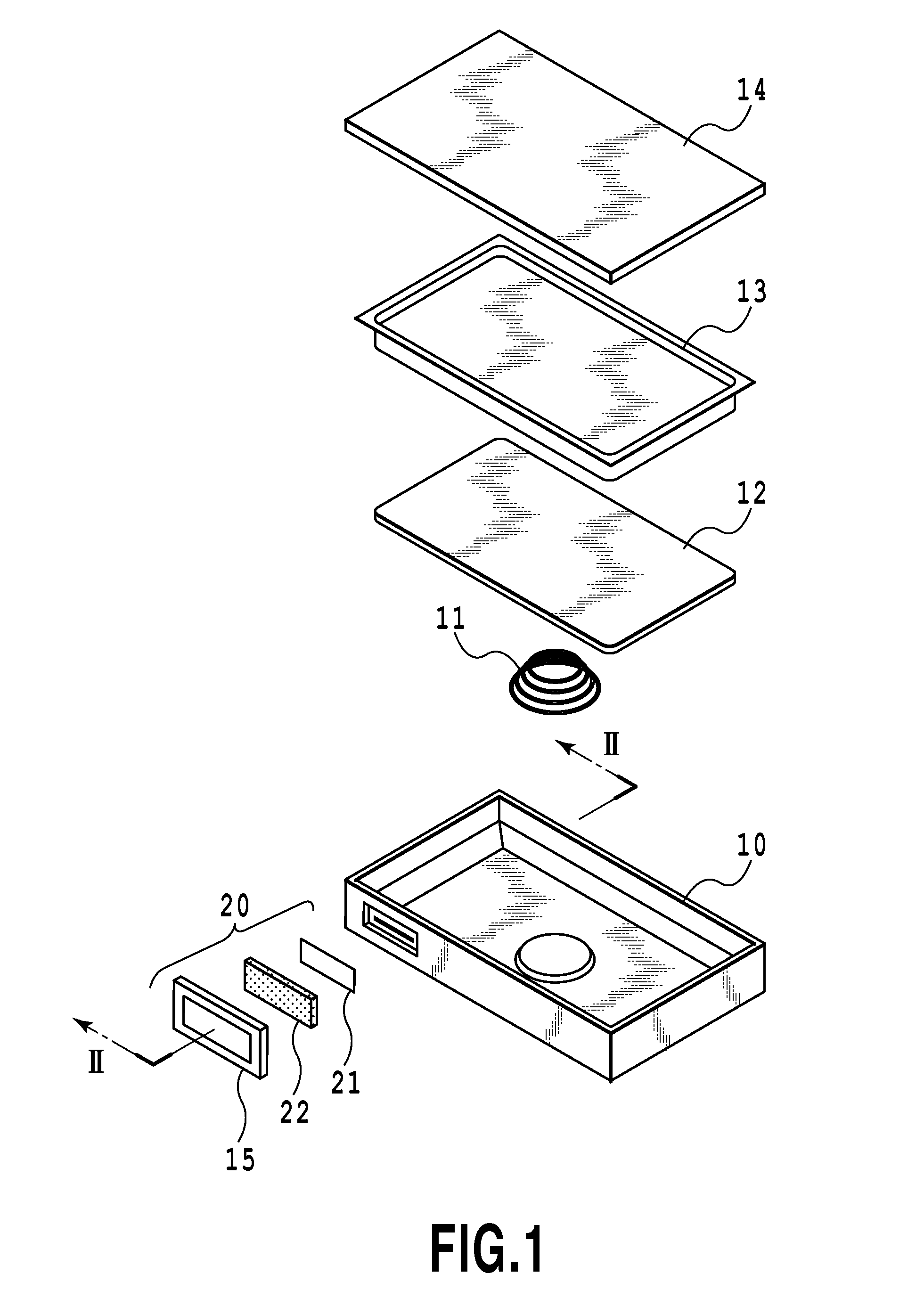
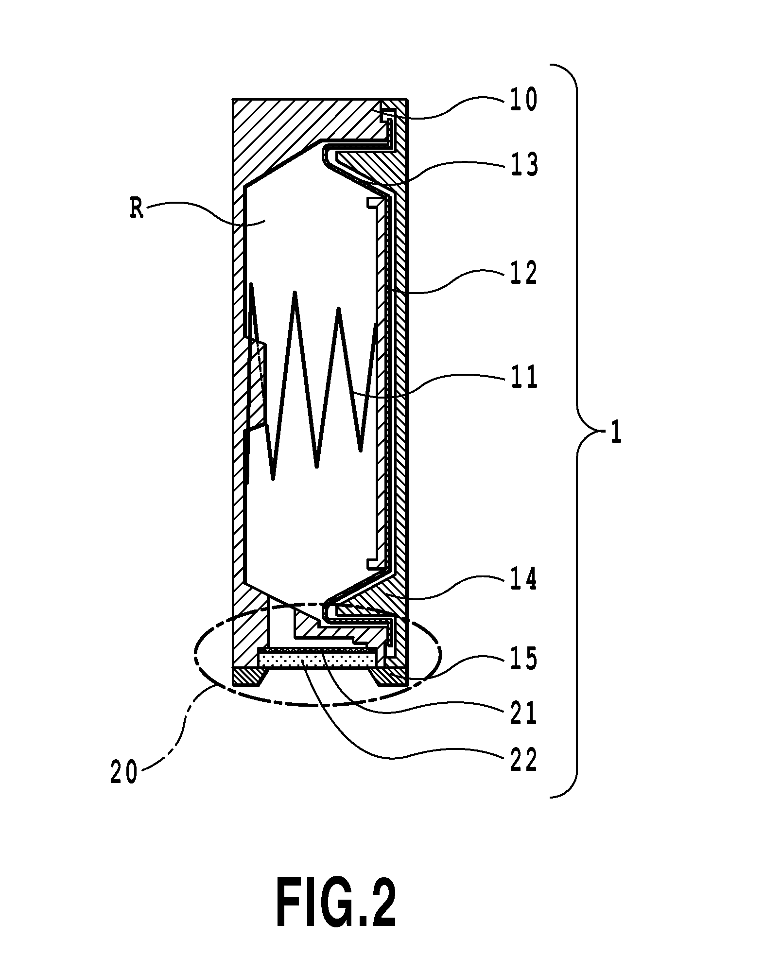
[0051]FIG. 10 is a diagram illustrating an example of the structure of an inkjet printing apparatus to which the present invention can be applied. The printing apparatus 150 is a serial scan type inkjet printing apparatus, which comprise guide shafts 151, 152 movably guiding a carriage 153 in the main scan direction α. The carriage 153 is reciprocated in the main scan direction α by a driving force transmission mechanism including a carriage motor, a belt for transmitting the driving force of the carriage motor, and the like. The carriage 153 can be detachably mounted with an inkjet print head (not shown) and ink tanks 1 for supplying ink to the print head. Four ink tanks 1 are mounted in the embodiment, but any number of ink tanks 1 mounted may be mounted as long as one or more ink tanks are mounted.
[0052]A print medium P is ins...
second embodiment
[0088]Next, a second embodiment of the present invention will be described with reference the accompanying drawings.
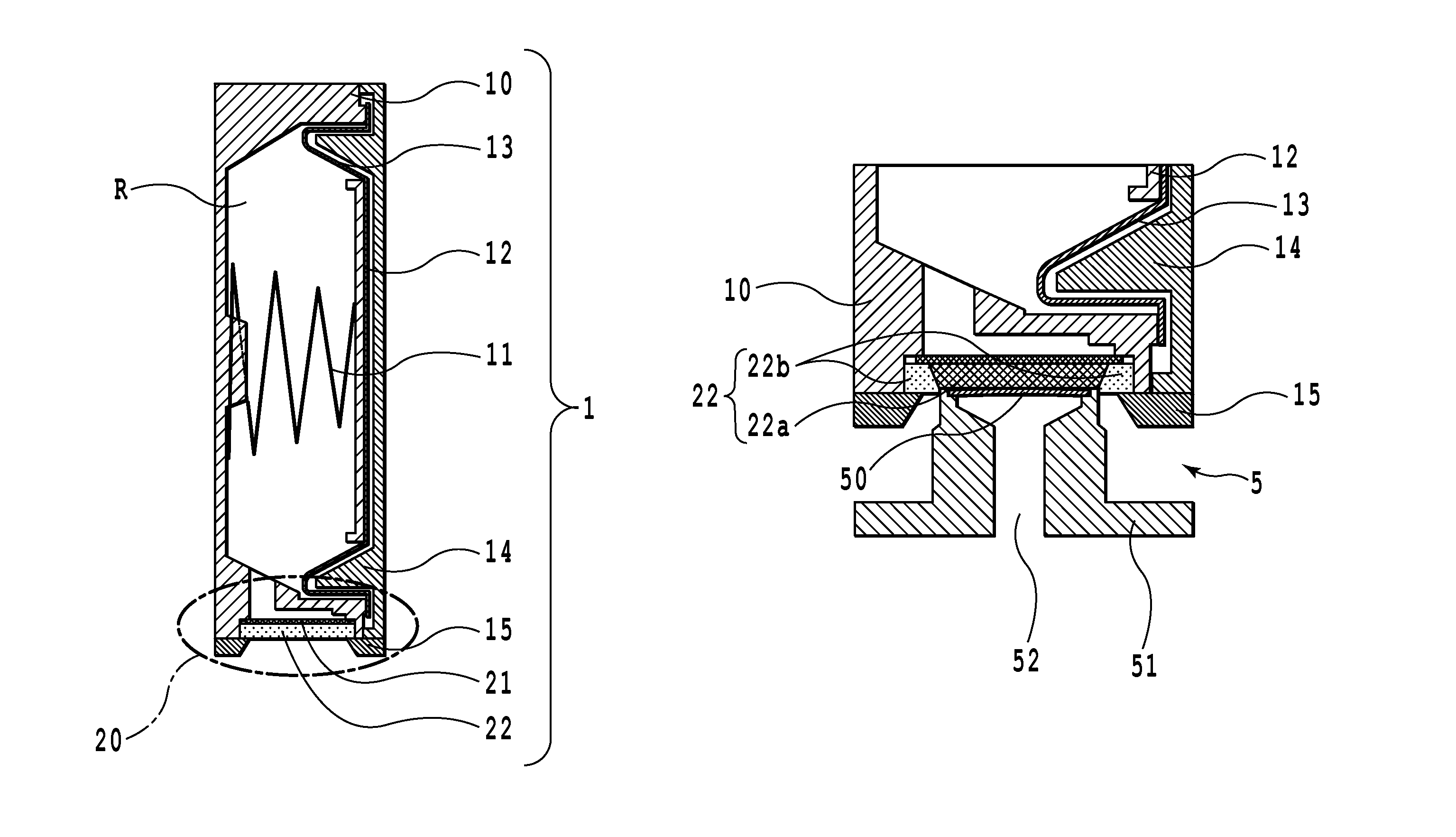
[0089]FIG. 7 is a graph showing negative pressure in the ink tank from the initial state when the ink tank according to the present invention is mounted on the print head 5 to the final state when the ink runs out. FIG. 8A to FIG. 8C are sectional views of the ink guide member respectively corresponding to points (e) to (g) on the negative-pressure curve in FIG. 7. FIG. 8A corresponds to the point (e) in FIG. 7 and illustrates “the tank-mounting initial state”. FIG. 8B corresponds to the point (f) in FIG. 7 and illustrates “the state in which the meniscus holding force of the non-compressed area of the ink guide member 22 falls below the negative pressure in the ink tank, and the ink in the ink guide member is consumed”. FIG. 8C corresponds to the point (g) in FIG. 7 and shows a cross section of “the ink tank after the ink has been used up”. The following description i...
PUM
 Abstract
Description
Claims
Application Information
 - R&D
- Intellectual Property
- Life Sciences
- Materials
- Tech Scout
- Unparalleled Data Quality
- Higher Quality Content
- 60% Fewer Hallucinations
Browse by: Latest US Patents, China's latest patents, Technical Efficacy Thesaurus, Application Domain, Technology Topic, Popular Technical Reports.
© 2025 PatSnap. All rights reserved.Legal|Privacy policy|Modern Slavery Act Transparency Statement|Sitemap|About US| Contact US: help@patsnap.com


