Boron nitride nanotubes

a boron nitride and nanotube technology, applied in the direction of boron compounds, polycrystalline material growth, crystal growth process, etc., can solve the problem of little progress in the scale-up of their synthesis

Active Publication Date: 2012-06-26
NASA +2
View PDF0 Cites 57 Cited by
  • Summary
  • Abstract
  • Description
  • Claims
  • Application Information

AI Technical Summary

Benefits of technology

[0008]It is a primary object of the present invention to provide what is not available in the art, viz., a synthetic process which provides a significant advancement in anticipation of kilogram-scale production of boron nitride nanotubes—a most important steppingstone toward the investigation of their properties in macroscopic practice and their ultimate commercial use.
[0022]Although nitrogen gas may be advantageously employed at a pressure greater than about 2 atmospheres but less than about 250 atmospheres, very excellent results are achieved if nitrogen gas is provided at a pressure from greater than about 2 atmospheres up to about 12 atmospheres.

Problems solved by technology

Since the announcement of the successful synthesis of high-aspect-ratio few-walled boron nitride nanotubes (FW-BNNTs) in 1995, little progress has been made in the scale-up of their synthesis.

Method used


Image

  • Boron nitride nanotubes
  • Boron nitride nanotubes
  • Boron nitride nanotubes

Examples


Embodiment Construction

should be read in the light of the accompanying Drawings, wherein:

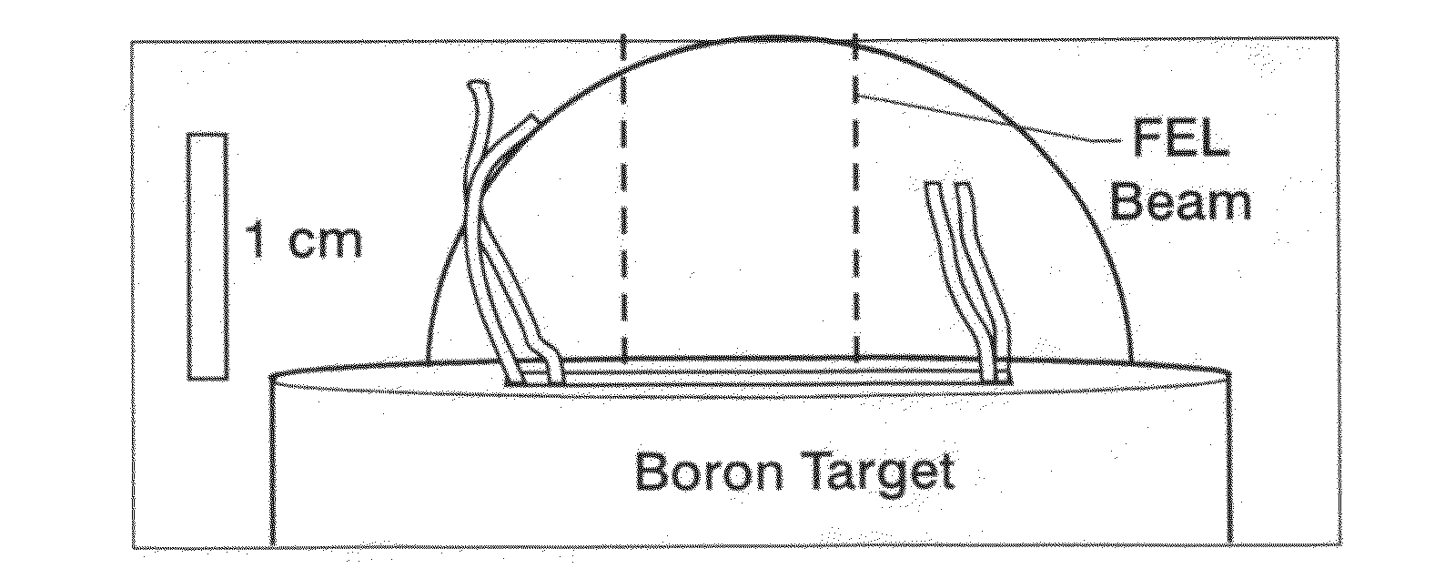
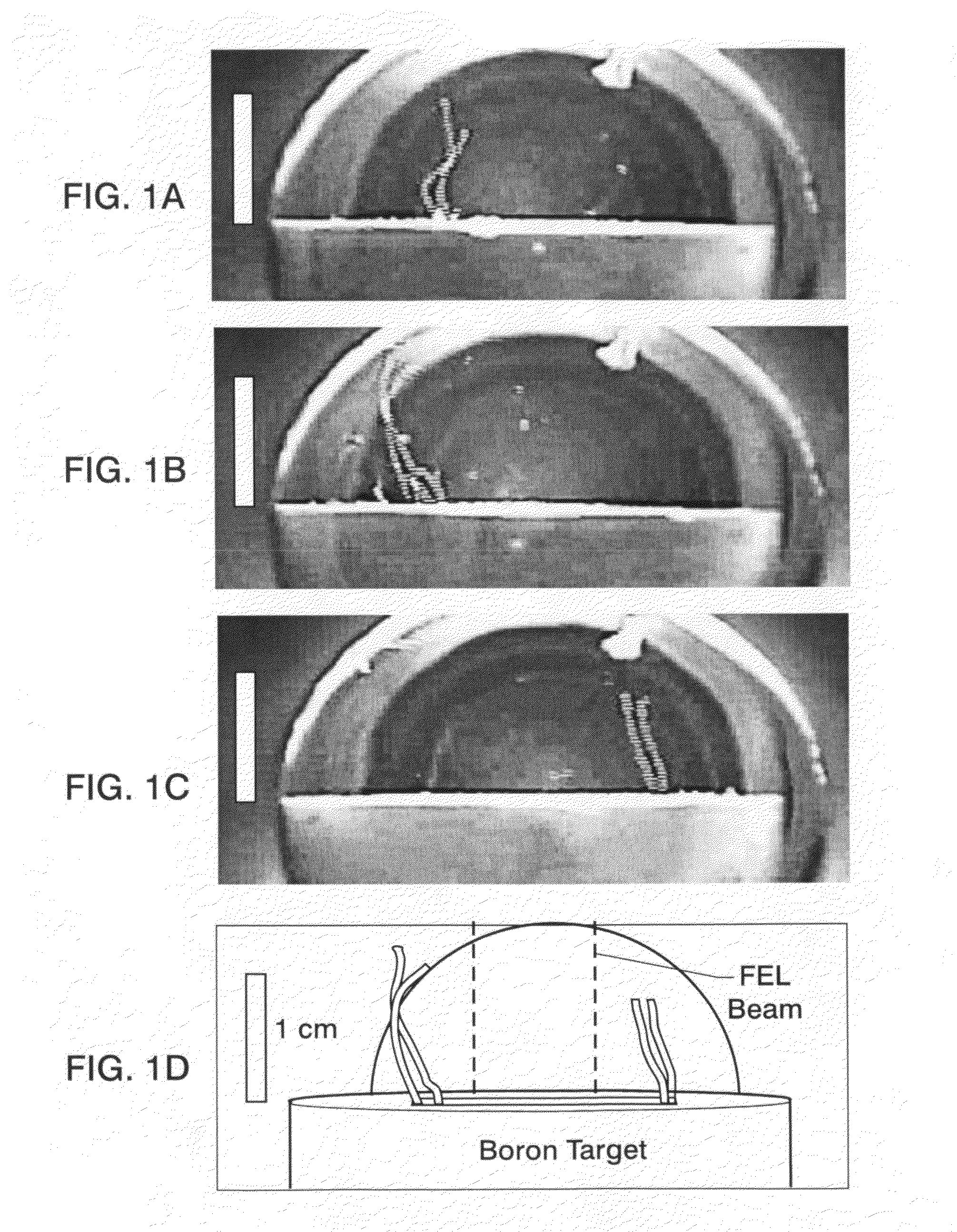
[0027]FIGS. 1A-1C are drawings made from still images taken from a video showing the formation of streamers of boron nitride nanotubes prepared according to the present invention. FIG. 1D is a schematic showing the relationship of a boron-containing target to a free electron laser (FEL) beam, according to one embodiment of the present invention; this figure also shows outlines of streamers of boron nitride nanotubes prepared according to the present invention. Scale bars are 1 centimeter in all figures.

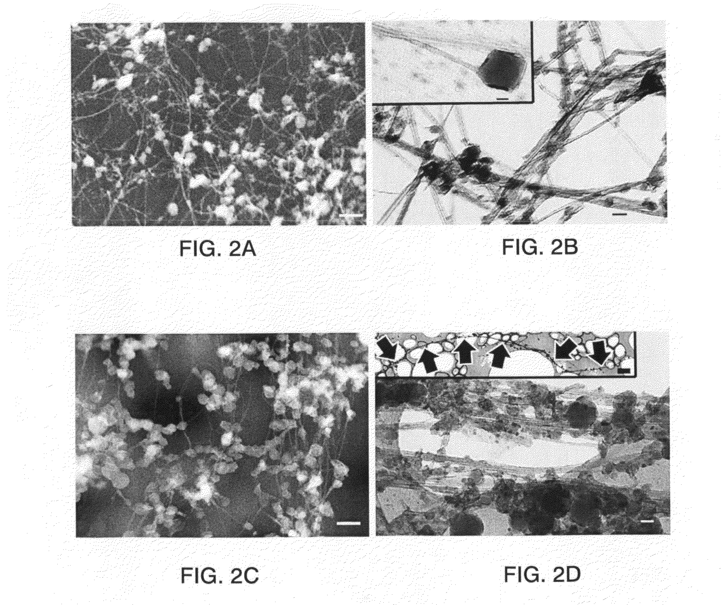
[0028]FIGS. 2A-2D are drawings made from high resolution scanning electron microscope (HRSEM) images. FIG. 2A presents raw streamer material, a network of boron nitride nanotubes and round nanoparticles; the scale bar is 200 nm; boron nitride target.FIG. 2B presents scanning transmission mode (STEM) images of the same material as in FIG. 2A; the scale bar is 20 nm; the inset of FIG. 2B shows individual boron nitride nan...


PUM

PropertyMeasurementUnit
pressureaaaaaaaaaa
pressureaaaaaaaaaa
pressureaaaaaaaaaa

Abstract

Boron nitride nanotubes are prepared by a process which includes:(a) creating a source of boron vapor;(b) mixing the boron vapor with nitrogen gas so that a mixture of boron vapor and nitrogen gas is present at a nucleation site, which is a surface, the nitrogen gas being provided at a pressure elevated above atmospheric, e.g., from greater than about 2 atmospheres up to about 250 atmospheres; and(c) harvesting boron nitride nanotubes, which are formed at the nucleation site.

Description

CROSS REFERENCE TO RELATED APPLICATION[0001]This Application claims the benefit of U.S. Provisional Application No. 60 / 930,206 filed on May 15, 2007 for “Boron Nitride Nanotubes”.STATEMENT REGARDING FEDERALLY SPONSORED RESEARCH OR DEVELOPMENT[0002]The U.S. Government has a paid-up license in this invention and the right in limited circumstances to require the patent owner to license others on reasonable terms as provided for by the terms of Cooperative Agreement No. NCC-1-02043 awarded by the National Aeronautics and Space Administration and Management and Operating Contract DE-AC05-060R23177 from the United States Department of Energy.BACKGROUND OF THE INVENTION[0003]1. Field of the Invention[0004]This invention relates generally to the production of nanostructures. It relates particularly to the formation of at least centimeter-long stranded boron nitride nanotube fibers.[0005]2. Description of the Related Art[0006]Since the announcement of the successful synthesis of high-aspect-...

Claims


Application Information

Patent Timeline
Patent Type & Authority Patents(United States)
IPC IPC(8): C01B21/064B01J19/12
CPCB82Y30/00C01B21/0641C30B29/602C30B23/00C30B29/403C01P2004/04C01P2004/13C01P2004/16C01P2004/133C01B35/146
Inventor SMITH, MICHAEL W.JORDAN, KEVINPARK, CHEOL
Owner NASA
Why Eureka
Try Eureka