Actively ventilated shoe

a technology of active ventilation and shoes, applied in the field of shoes, can solve the problems of preventing the heat and humidity from being sufficiently transported away from the foot to efficiently, the risk of foot diseases, and the inability to manufacture shoes, and achieve the effect of less customization of the clima

Inactive Publication Date: 2012-07-03
ADIDAS
View PDF60 Cites 33 Cited by
  • Summary
  • Abstract
  • Description
  • Claims
  • Application Information

AI Technical Summary

Benefits of technology

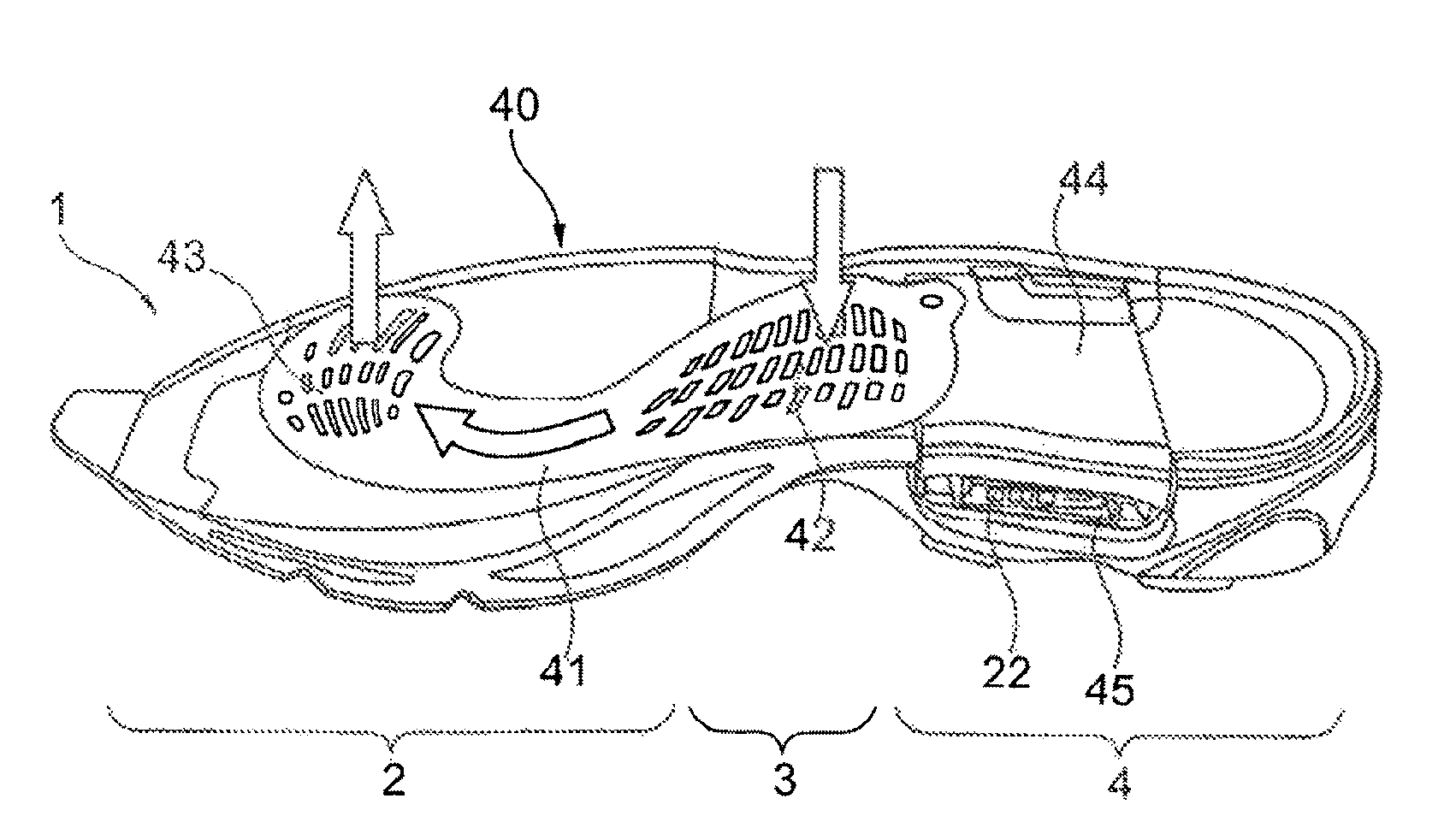
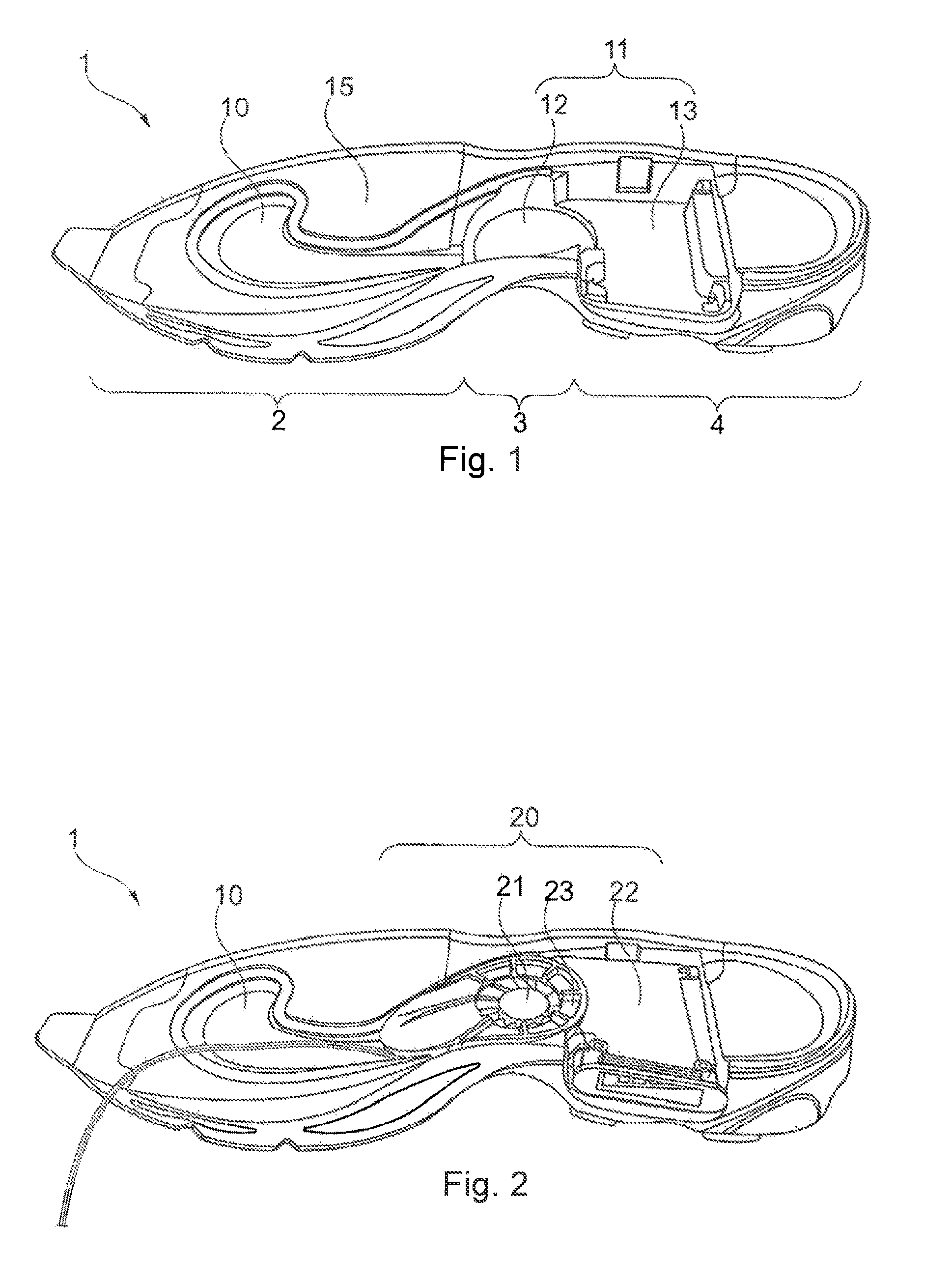
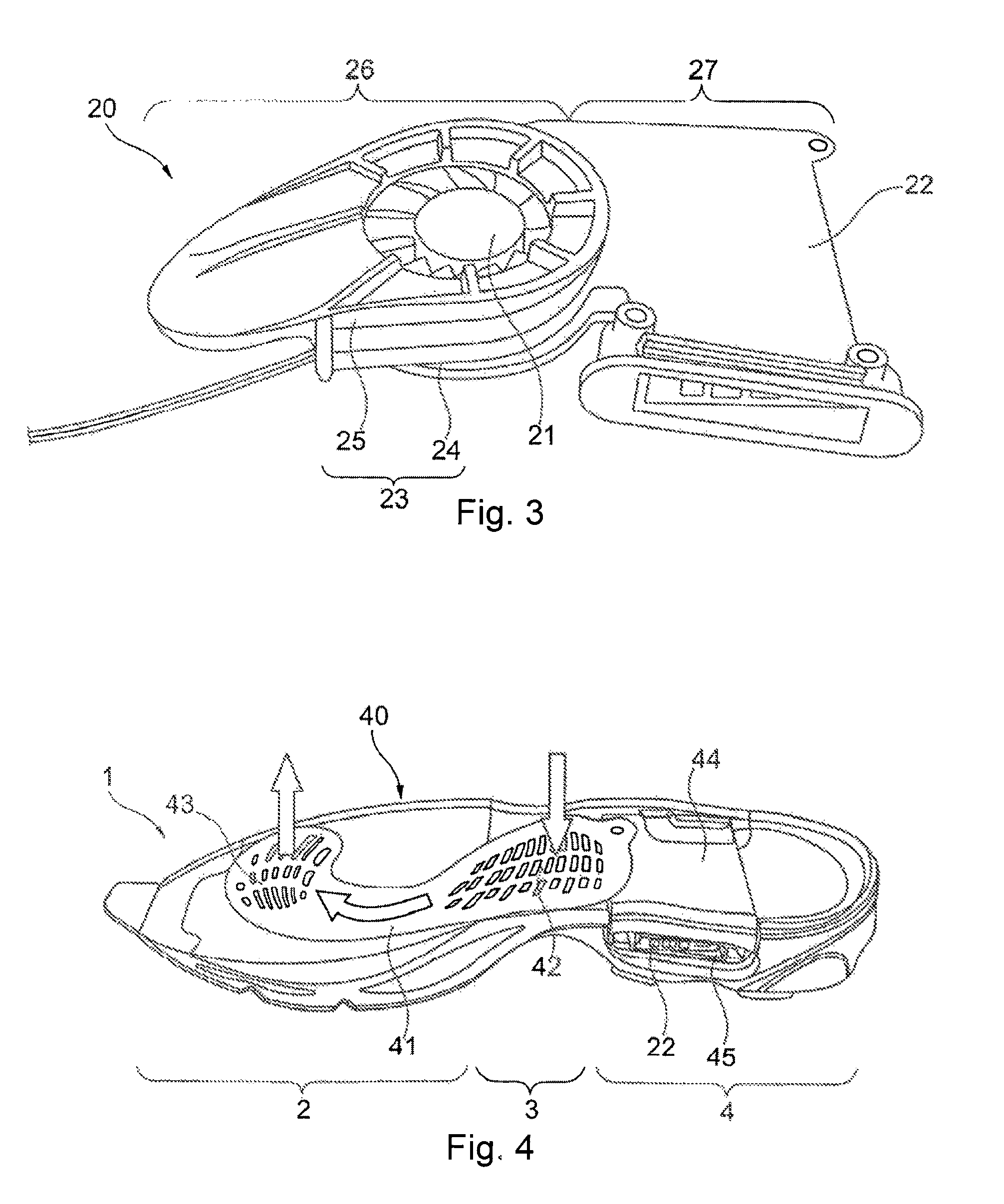
[0018]Arranging the active ventilation element in the midfoot area may be advantageous since this area experiences neither the compression forces that occur when the shoe hits the ground nor the deformations in the forefoot area when the heel lifts from the ground. It may have the further advantage of leaving sufficient volume in the heel area for materials which cushion the heel when the shoe hits the ground. Further, arranging the active ventilation element in the midfoot area provides effective ventilation of the shoe by facilitating an air channel from the midfoot area to the forefoot area. These two areas are particularly advantageous for ventilation since the foot exerts a lower pressure to the sole in these areas of the shoe and thereby a more efficient exchange of air is provided.
[0034]In an embodiment of the present invention, the input device controls a control unit of another shoe, for example, wirelessly by transmitting corresponding control signals from the first shoe to the other shoe. This avoids the need to input user-specific adjustments for the other shoe.

Problems solved by technology

However, in spite of these important improvements, companies have been unsuccessful in manufacturing shoes that, in addition to providing necessary damping and support to the foot, also provide a comfortable climate for the foot.
On the contrary, use of the foamed plastic materials common in modern sports shoes prevents heat and humidity from being sufficiently transported away from the foot to efficiently avoid excess heat buildup, unpleasant odor or the risk of diseases of the foot.
This is particularly problematic in athletic shoes due to the increased body activity when participating in sports, which causes an increase in heat and humidity in the shoe.
In some cases, one disadvantage of these systems is that the air inlet and / or air outlet openings are arranged on the outside of the shoe.
In such a configuration, there is a risk that moisture and dirt may enter the openings and thus the interior of the shoe.
This can damage or even destroy the ventilation system.
However, even in this arrangement there is a danger that moisture and dirt may enter the tube.
In some cases, one disadvantage of this approach is that the heel portion of a shoe generally experiences the highest impact forces during the gait cycle, and these forces can interfere with the operation of the ventilation system.
Because the ventilation system described in U.S. Pat. No. 3,273,264 occupies a substantial volume of the heel, the system has the undesirable effect of reducing the amount of cushioning material that can be placed in the heel.
However, the fan can be easily damaged due to its positioning on the toe or exterior side of the shoe.
There is also a danger that moisture and dirt will be sucked in by the fan.
Furthermore, in this arrangement no fresh air is transported to the underside of the foot, which is where the most moisture collects and most heat is generated.
The described systems of actuators and sensors are directed to medical therapy and do not provide solutions for a controlled ventilation of shoes.
The above-described approaches for ventilation suffer from several disadvantages, including lack of protection from moisture and dirt, insufficient air circulation inside the shoe, and insufficient cushioning in the heel area.
Furthermore, the possibilities for controlling ventilation are limited, since a simple temperature control does not satisfy the complex and variable requirements for maintaining a comfortable climate in a shoe.
Several of the shoes described above can be time-consuming to manufacture because the components of the ventilation systems are distributed in different locations of the shoe and therefore add steps to the manufacturing process.

Method used


Image

  • Actively ventilated shoe
  • Actively ventilated shoe
  • Actively ventilated shoe

Examples


Embodiment Construction

[0048]The present invention is now described with references to the Figures. As follows, embodiments of the present invention of a running shoe are described in more detail. While specific configurations and arrangements can be used without departing from the spirit and scope of the invention, it will be apparent to a person skilled in the relevant art that this invention can also be employed in other applications. The following examples are illustrative, but not limiting, of the structure and methods of the present invention. Other suitable modifications and adaptations of the variety of conditions and parameters normally encountered in the field, and which would be apparent to those skilled in the art, are within the spirit and scope of the invention.

[0049]It will be appreciated that the present invention is not limited to running shoes or sports shoes. Rather, embodiments of the present invention may be used in any suitable article of footwear, including, but not limited to, shoe...


PUM


Abstract

The invention relates to an article of footwear, in particular a sports shoe, wherein the article of footwear includes a ventilation system with at least one active ventilation element arranged in a midfoot area of the article of footwear. Furthermore, the article of footwear includes at least one air channel with an inlet and an outlet which are arranged in the sole area in the interior of the article of footwear. The active ventilation element is arranged such that air is sucked from the interior of the article of footwear through the inlet and is blown into the interior of article of footwear shoe through the outlet.

Description

BACKGROUND OF THE INVENTION[0001]1. Field of the Invention[0002]Embodiments of the present invention generally relate to footwear, and more specifically to an actively ventilated shoe, in particular an athletic shoe.[0003]2. Background Art[0004]The technical development of shoes, in particular sports shoes, has advanced considerably in recent years. Modern shoe constructions are available that are adapted to compensate for the mechanical stress on a foot that arises when participating in various sporting activities. These shoe constructions provide a high degree of functionality and wearing comfort.[0005]However, in spite of these important improvements, companies have been unsuccessful in manufacturing shoes that, in addition to providing necessary damping and support to the foot, also provide a comfortable climate for the foot. On the contrary, use of the foamed plastic materials common in modern sports shoes prevents heat and humidity from being sufficiently transported away from...

Claims


Application Information

Patent Timeline
Patent Type & Authority Patents(United States)
IPC IPC(8): A43B7/06
CPCA43B3/0005A43B7/081A43B17/08A43B3/34
Inventor LEIMER, ROBERTROBINSON, TIMOTHY KELVINMICHEL, FRANK INGOMANZ, GERD RAINERGORDON, JOSH ROBERTALLEN, TOMHARNISCH, MARTINBLINN, JOERG
Owner ADIDAS
Why Eureka
Try Eureka