Vibrating gyroscope with quadrature signals reduction

a vibration gyroscope and quadrature technology, applied in the field of rotational motion sensors, can solve the problems of only detrimental unwanted displacement of the proof mass

Inactive Publication Date: 2012-07-03
COLIBRYS
View PDF5 Cites 6 Cited by
  • Summary
  • Abstract
  • Description
  • Claims
  • Application Information

AI Technical Summary

Benefits of technology

[0024]The solution has the advantage that only the position of a specific point of the proof mass along a single axis needs to be controlled. As other displacements of the proof mass are allowed, this gives more possibilities to design a gyroscope insensitive to quadrature.
[0027]Furthermore, the proof mass may be associated to a second vibrating part whose displacements are not detected but increases the moment of inertia of the vibrating system, giving even more design freedom.
[0030]An active electronic quadrature reduction circuit may be used additionally, in order to cancel or reduce quadrature forces which may cause residual displacements of the proof mass.

Problems solved by technology

More specifically, it has been found that unwanted displacements of the proof mass are only detrimental if the neutral point of the proof mass moves along the sense axis.

Method used


Image

  • Vibrating gyroscope with quadrature signals reduction
  • Vibrating gyroscope with quadrature signals reduction
  • Vibrating gyroscope with quadrature signals reduction

Examples


Embodiment Construction

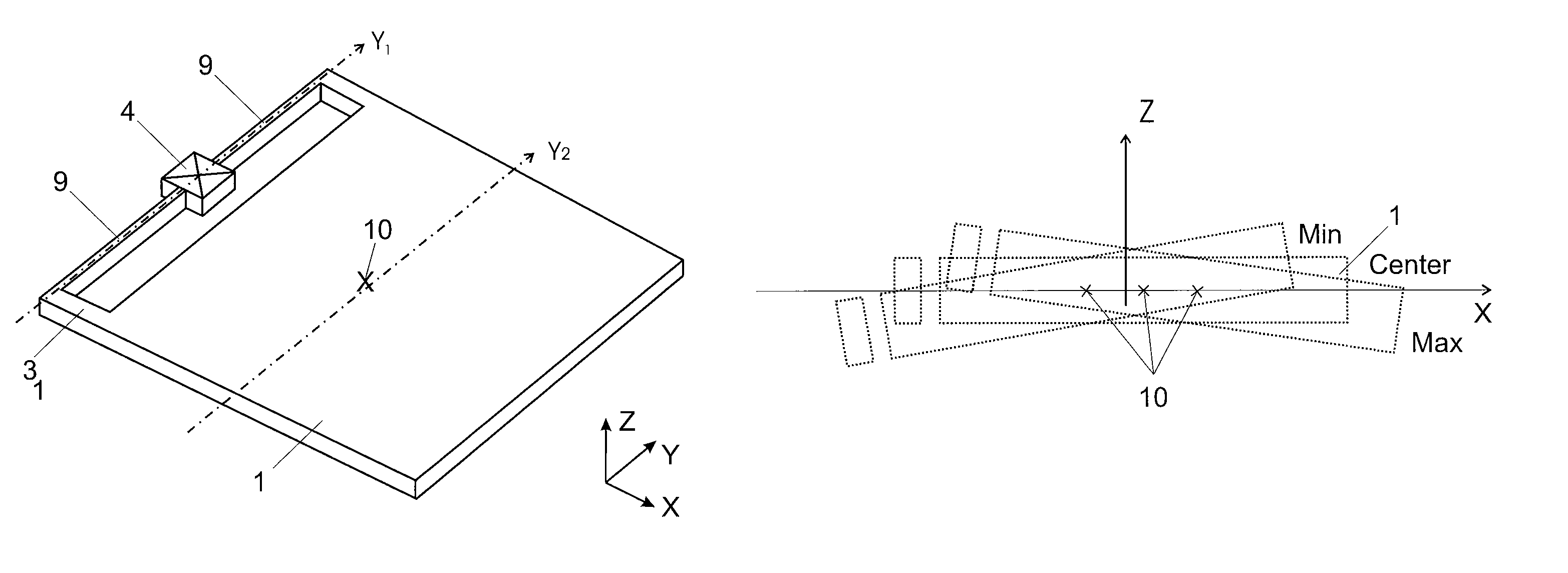
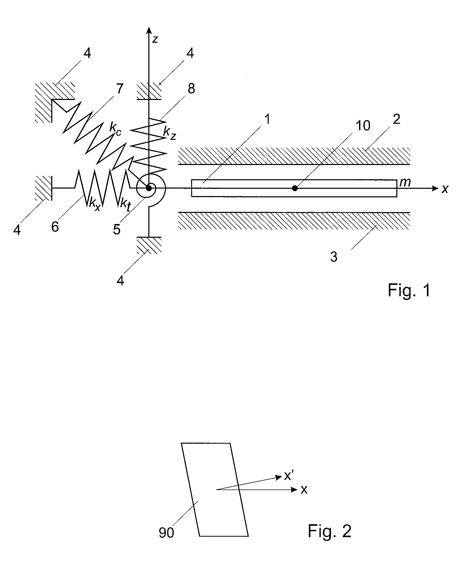
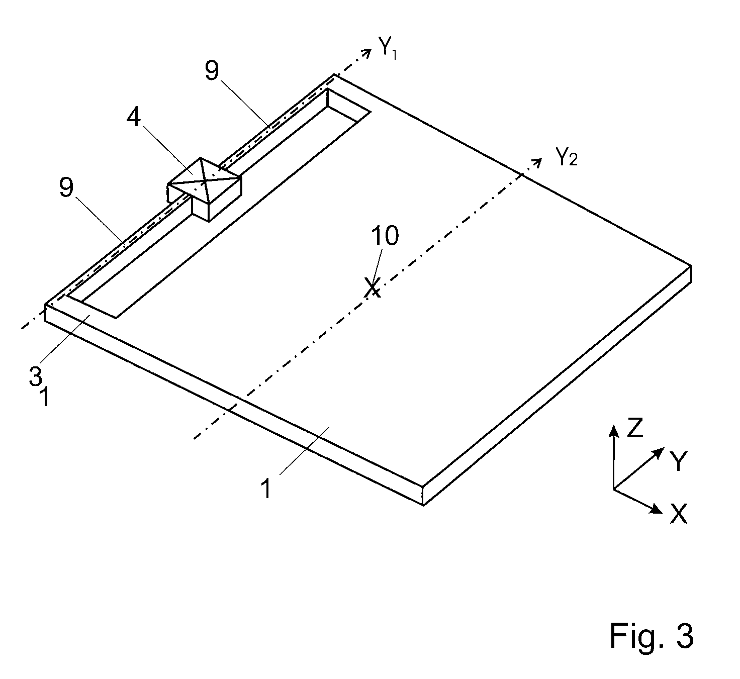
[0039]FIG. 1 schematically illustrates a model of an example of vibrating gyroscope, which may be realized for instance but not necessarily using mems-technology. The illustrated gyroscope generally comprises a proof mass 1 which is suspended by the springs 5, 6, 7, 8 in such a way that the proof mass has essentially three degrees of freedom relative to the substrate 4; the other degrees of freedom are either undetectable or otherwise irrelevant. The spring suspension system is schematically represented here by four equivalent springs, namely a first longitudinal spring 6 with a constant kx along the x axis, a second coupling spring 7 with a constant kc corresponding to quadrature forces in the z direction due to a deflection in the x direction, a third longitudinal spring 8 with a constant kz along the z axis, and a fourth spring 5 with a constant kt acting on rotations in a x-z plane, around an axis close to the spring attachment point. In this document, the x axis will also be ca...


PUM


Abstract

A vibrating gyroscope includes a proof mass (1); a spring suspension system (5, 6, 7, 8; 9) for suspending the proof mass; an electrical drive mechanism for vibrating the proof mass along a drive axis (x); and electrodes (2, 3) for building together with at least a part of the proof mass (1) a capacitance system for detecting moves of the proof mass along a sense axis (z) perpendicular to the drive axis. The gyroscope is arranged so that quadrature forces generate displacements of the proof mass without substantially displacing the neutral point (10) of the proof mass along the sense axis (z). This may be achieved by tilting the proof mass while keeping its neutral point at a constant position along the sense axis, or by applying a constant electrostatic force.

Description

CROSS-REFERENCE TO RELATED APPLICATIONS[0001]This application claims the priority of EP08152320 filed Mar. 5, 2008, the content of which is enclosed by reference.[0002]The present application is further related to European Patent Application EP08152329 filed Mar. 5, 2009, the content of which is included herewith by reference.BACKGROUND OF THE INVENTION[0003]1. Field of the Invention[0004]The present invention relates generally to rotational motion sensor, such as gyroscopes, and more specifically, but not exclusively, to micromachined, mems-based, sensing vibrating gyroscopes for measuring angular velocity and, optionally, acceleration.[0005]2. Description of Related Art[0006]Vibrating gyroscopes rely on the vibration of a proof mass in one direction and in detecting the Coriolis force generated in a perpendicular direction by the rotational speed. Vibrating gyroscopes are formed, for example, by etching a semiconductor to form a proof mass suspended by a spring system, such as ela...

Claims


Application Information

Patent Timeline
Patent Type & Authority Patents(United States)
IPC IPC(8): G01C19/56
CPCG01C19/56G01C19/5642
Inventor RUDOLF, FELIXFROSIO, ROBERTOZWAHLEN, PASCALDUTOIT, BERTRAND
Owner COLIBRYS
Why Eureka
Try Eureka