Ambience lighting system for a display device

a technology of display device and ambient light, which is applied in the field of ambient light system for display device, can solve the problems of reducing the possibility of adding a reflector, and achieve the effects of reducing complexity and thickness of construction, optimal light distribution, and improving viewing experien

Active Publication Date: 2011-08-11
TOP VICTORY INVESTMENTS
View PDF3 Cites 6 Cited by
  • Summary
  • Abstract
  • Description
  • Claims
  • Application Information

AI Technical Summary

Benefits of technology

[0011]Accordingly, the fact that the light sources which in one embodiment comprises Light Emitting Diodes (LED), and the reflector are not integrated into the front part, but at the rear part makes it possible to implement the ambience lighting system in ultra thin display devices. Also, it is possible to select an internal arrangement between the at least one light source and the reflector such that the light path between the reflector and to the wall will be sufficiently long although the display device is placed very close to the wall, i.e. this lighting system allows much more design freedom. This means that all undesired light effect, e.g. LED spots, become invisible and that the required light path length necessary to minimize the number of light sources is fulfilled. Also, by moving the light sources away from the edge of the display device and e.g. towards an area within the central rear side of the display device, the ambience light sources will be hidden from a direct view.
[0014]Such an optical element may be used for transporting, bending, converging or diverging the emitted light beams. By situating the at least one light source towards the central back section and the reflector at the periphery of the rear side, the bulky ambilight parts (PCB, LEDs) that are typically used in prior art ambience lighting systems is moved away from the edge to the central area of the TV back, which is already thicker, while leaving the smaller reflector at the edge. As mentioned above, an important condition is that the light becomes transferred now over a longer distance between source and reflector without hitting the wall behind the TV. Therefore, the insertion of such an optical element is of a particular advantage.
[0025]In one embodiment, the reflector itself is the back of the display device. Thus, the reflector and the back of the display device act as a common element, which results in that the complexity and thickness of the construction is reduced.
[0026]In one embodiment, the end of the reflector at the periphery of the rear side of the display device is curved shaped pointing away from the wall behind the display devices. Thus, a sudden brightness at the wall can be avoided and therefore the viewing experience is improved.
[0031]Accordingly, using textures allows making some specific patterns which might even be adapted for different users. The diffuse finish may be used to make the reflected light more “soft” and thus unwanted light patterns caused by shadows or mirror irregularities may be avoided.

Problems solved by technology

Finally, moving the TVs closer to the wall reduces the possibilities of adding a reflector.

Method used


Image

  • Ambience lighting system for a display device
  • Ambience lighting system for a display device
  • Ambience lighting system for a display device

Examples


Embodiment Construction

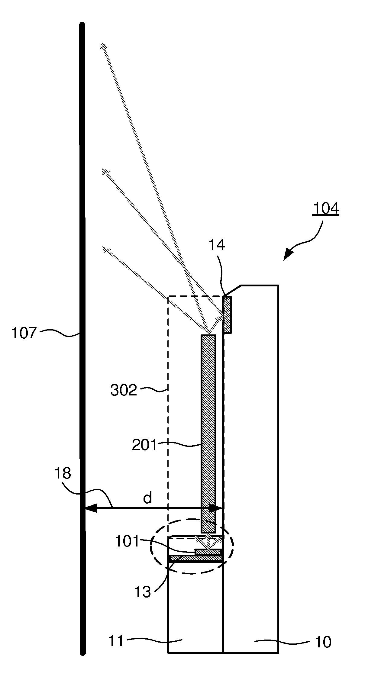
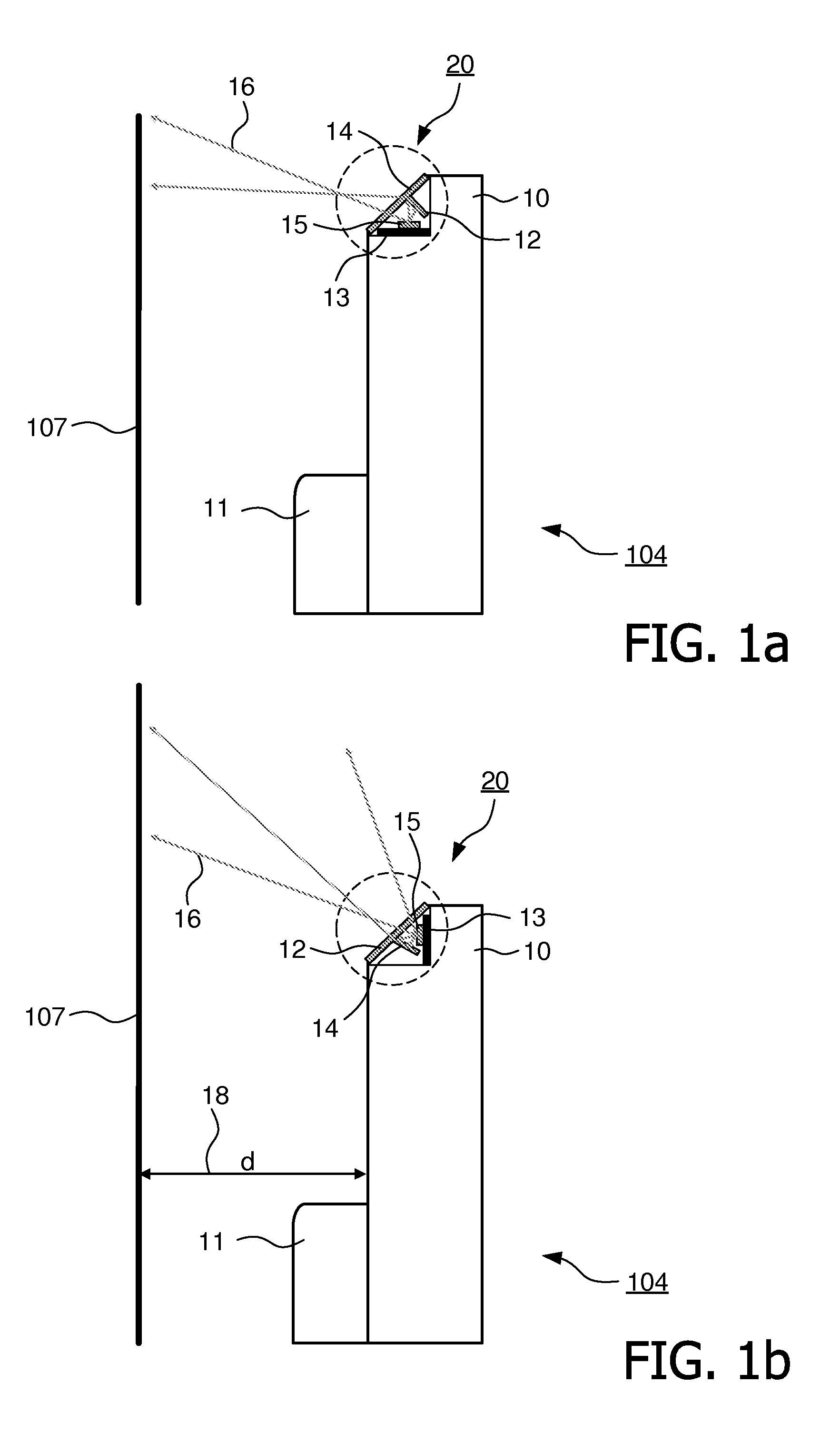
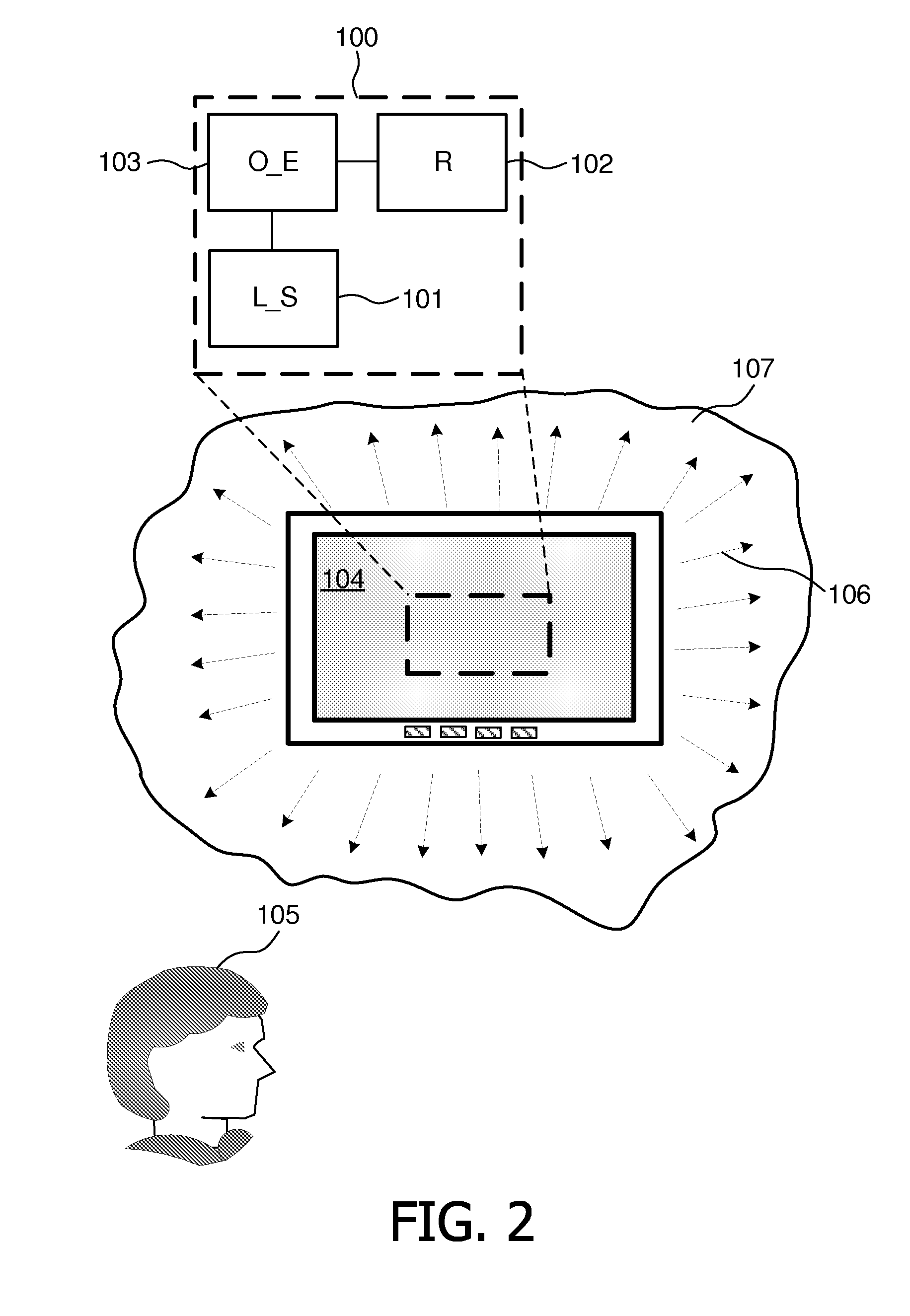
[0044]FIG. 2 shows an ambience lighting system 100 for a display device 104 according to the present invention, where the ambience lighting system 100 is adapted for emitting an ambience light, indicated by arrows 106, onto a wall 107 behind the display device 104. The display device may be selected from: a LCD device, a plasma device, an organic light-emitting diode (OLED) device, a projection screen, a computer monitor and the like. By the term wall is meant any kind of surface which reflects the light towards a viewer 105 located in front of the display device 104.

[0045]The ambience lighting system 100 comprises at least one light source (L_S) 101 and a reflector (R) 102, both being situated at the rear side of the display device 107. In one embodiment, the ambience lighting system 100 further comprises at least one optical element (O_E) 103 placed between the at least one light source (L_S) 101 and the reflector (R) 102 such that the light of the light beams enters the optical e...


PUM


Abstract

This invention relates to an ambience lighting system for a display device for emitting an ambience light onto a wall behind the display device. Light sources are placed at the rear side of the display device along with a reflector, where the internal arrangement of the light sources and the reflector is such that when the display device is placed in proximity to the wall the light emitted by the at least one light source becomes reflected by the reflector towards the wall such that the reflected light at least partly peripherally surrounds the viewing area of the display device.

Description

FIELD OF THE INVENTION [0001]The present invention relates to an ambience lighting system for a display device for emitting an ambience light onto a wall behind the display device.BACKGROUND OF THE INVENTION [0002]In the recent years, so-called AmbiLight TVs have been introduced to the market. Such TVs include light sources arranged at the periphery of the TVs, which emit an ambience light onto the wall behind the TVs such that the emitted light matches the video being shown. The effect is larger virtual screen and a more immersive viewing experience.[0003]The first generation of AmbiLight TVs required the AmbiLight system to be located near the edge of the TVs and pointing towards the wall next to the TVs. To reduce hotspot visibility, later on there was a move to keep this location but point them towards the wall behind the set and use reflectors to get the light on the wall next to the TVs. The internal arrangement of these components is such that an ambience light is emitted ont...

Claims


Application Information

Patent Timeline
Patent Type & Authority Applications(United States)
IPC IPC(8): G09F13/04
CPCF21V7/0008F21V33/0052H04N9/73G02F1/1336H04N5/58F21Y2101/02F21Y2115/10
Inventor KWISTHOUT, CORNELIS WILHELMUSOVERES, THEODORUS FRANCISCUS EMILIUS MARIANUIJENS, PETRUS GERARDUS JOSEPHUS MARIA
Owner TOP VICTORY INVESTMENTS
Why Eureka
Try Eureka